Philips Semiconductors
SC16C754
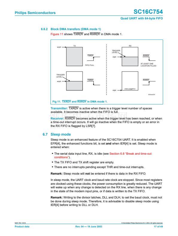
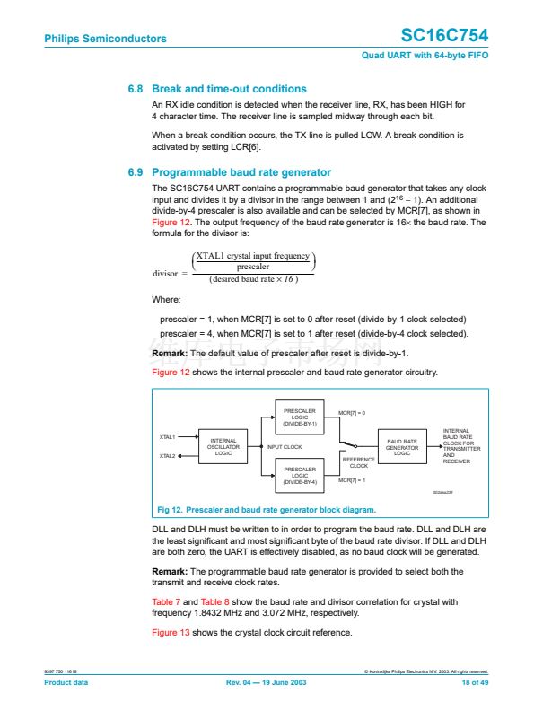
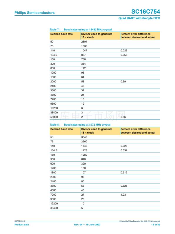
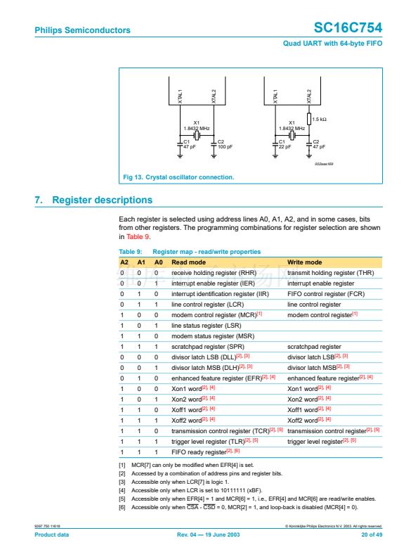
Quad UART with 64-byte FIFO
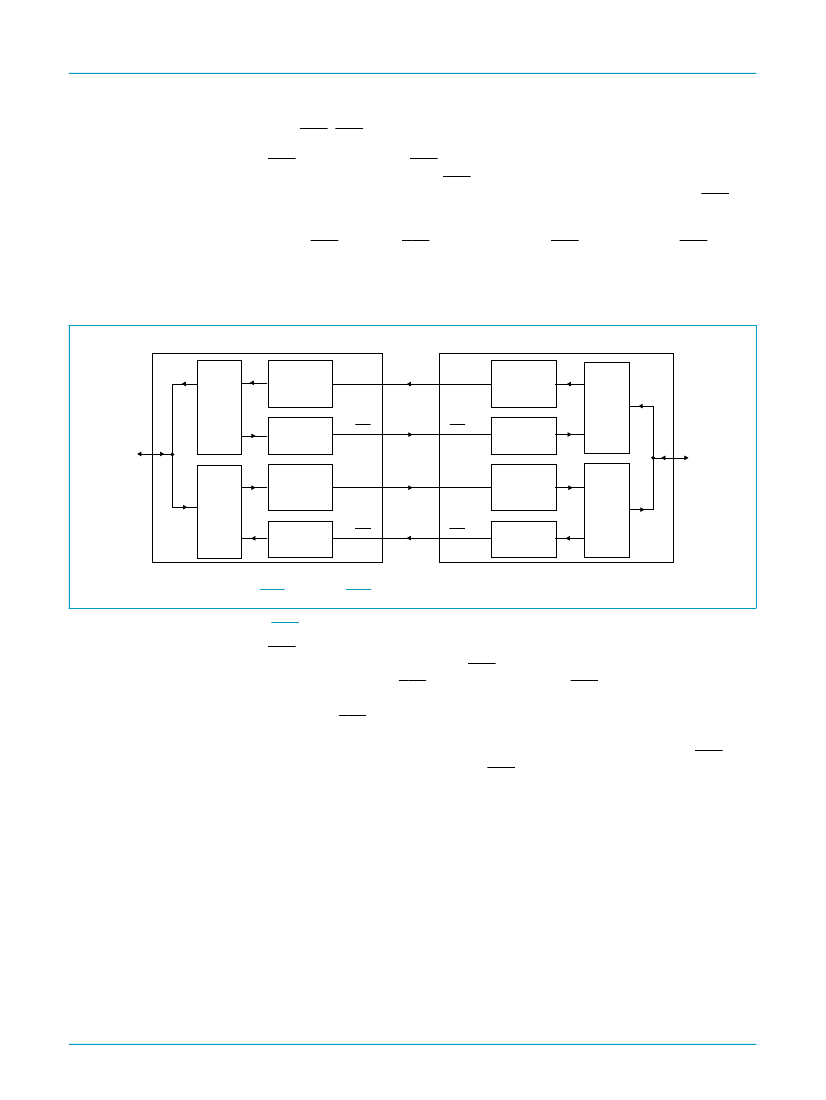
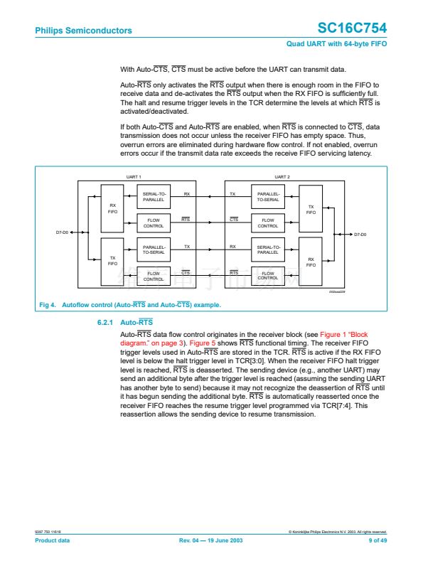
With Auto-CTS, CTS must be active before the UART can transmit data.
Auto-RTS only activates the RTS output when there is enough room in the FIFO to
receive data and de-activates the RTS output when the RX FIFO is suf铿乧iently full.
The halt and resume trigger levels in the TCR determine the levels at which RTS is
activated/deactivated.
If both Auto-CTS and Auto-RTS are enabled, when RTS is connected to CTS, data
transmission does not occur unless the receiver FIFO has empty space. Thus,
overrun errors are eliminated during hardware 铿俹w control. If not enabled, overrun
errors occur if the transmit data rate exceeds the receive FIFO servicing latency.
UART 1
UART 2
SERIAL-TO-
PARALLEL
RX
FIFO
FLOW
CONTROL
D7-D0
RX
TX
PARALLEL-
TO-SERIAL
TX
FIFO
RTS
CTS
FLOW
CONTROL
D7-D0
PARALLEL-
TO-SERIAL
TX
FIFO
FLOW
CONTROL
TX
RX
SERIAL-TO-
PARALLEL
RX
FIFO
CTS
RTS
FLOW
CONTROL
002aaa228
Fig 4. Auto铿俹w control (Auto-RTS and Auto-CTS) example.
6.2.1
Auto-RTS
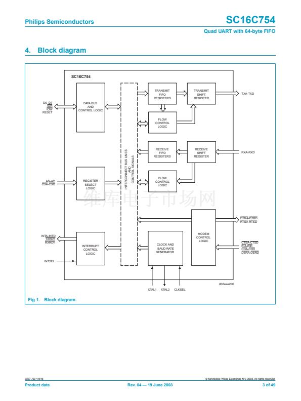
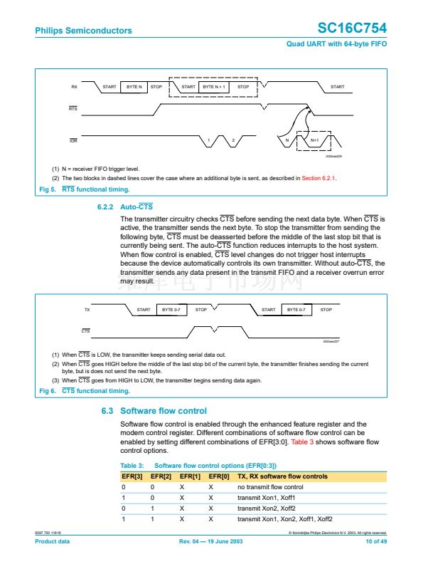
Auto-RTS data 铿俹w control originates in the receiver block (see
Figure 1 鈥淏lock
diagram.鈥?on page 3). Figure 5
shows RTS functional timing. The receiver FIFO
trigger levels used in Auto-RTS are stored in the TCR. RTS is active if the RX FIFO
level is below the halt trigger level in TCR[3:0]. When the receiver FIFO halt trigger
level is reached, RTS is deasserted. The sending device (e.g., another UART) may
send an additional byte after the trigger level is reached (assuming the sending UART
has another byte to send) because it may not recognize the deassertion of RTS until
it has begun sending the additional byte. RTS is automatically reasserted once the
receiver FIFO reaches the resume trigger level programmed via TCR[7:4]. This
reassertion allows the sending device to resume transmission.
9397 750 11618
漏 Koninklijke Philips Electronics N.V. 2003. All rights reserved.
Product data
Rev. 04 鈥?19 June 2003
9 of 49


 1
1
 2
2
 3
3
 4
4
 5
5
 6
6
 7
7
 8
8
 9
9
 10
10
 11
11
 12
12
 13
13
 14
14
 15
15
 16
16
 17
17
 18
18
 19
19
 20
20
 21
21
 22
22
 23
23
 24
24
 25
25
 26
26
 27
27
 28
28
 29
29
 30
30
 31
31
 32
32
 33
33
 34
34
 35
35
 36
36
 37
37
 38
38
 39
39
 40
40
 41
41
 42
42
 43
43
 44
44
 45
45
 46
46
 47
47
 48
48
 49
49
