Philips Semiconductors
SC16C754
Quad UART with 64-byte FIFO
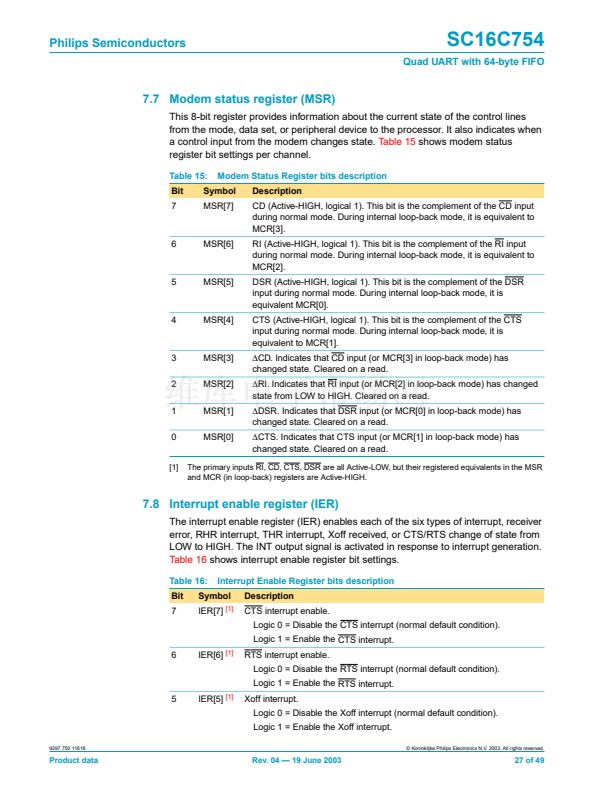
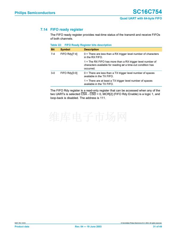
7.6 Modem control register (MCR)
The MCR controls the interface with the mode, data set, or peripheral device that is
emulating the modem.
Table 14
shows modem control register bit settings.
Table 14:
Bit
7
Modem Control Register bits description
Symbol
MCR[7]
[1]
Description
Clock select.
Logic 0 = Divide-by-1 clock input.
Logic 1 = Divide-by-4 clock input.
6
MCR[6]
[1]
TCR and TLR enable.
Logic 0 = no action.
Logic 1 = Enable access to the TCR and TLR registers.
5
MCR[5]
[1]
Xon Any.
Logic 0 = Disable Xon Any function.
Logic 1 = Enable Xon Any function.
4
MCR[4]
Enable loop-back.
Logic 0 = Normal operating mode.
Logic 1 = Enable local loop-back mode (internal). In this mode the
MCR[3:0] signals are looped back into MSR[7:4] and the TX output
is looped back to the RX input internally.
3
MCR[3]
IRQ enable OP.
Logic 0 = Forces INTA-INTB outputs to the 3-State mode and OP
output to HIGH state.
Logic 1 = Forces the INTA-INTB outputs to the active state and OP
output to LOW state. In loop-back mode, controls MSR[7].
2
MCR[2]
FIFO Ready enable.
Logic 0 = Disable the FIFO Rdy register.
Logic 1 = Enable the FIFO Rdy register.
In loop-back mode, controls MSR[6].
1
MCR[1]
RTS
Logic 0 = Force RTS output to inactive (HIGH).
Logic 1 = Force RTS output to active (LOW).
In loop-back mode, controls MSR[4]. If Auto-RTS is enabled, the
RTS output is controlled by hardware 铿俹w control.
0
MCR[0]
DTR
Logic 0 = Force DTR output to inactive (HIGH).
Logic 1 = Force DTR output to active (LOW).
In loop-back mode, controls MSR[5].
[1]
MCR[7:5] can only be modi铿乪d when EFR[4] is set, i.e., EFR[4] is a write enable.
9397 750 11618
漏 Koninklijke Philips Electronics N.V. 2003. All rights reserved.
Product data
Rev. 04 鈥?19 June 2003
26 of 49


 1
1
 2
2
 3
3
 4
4
 5
5
 6
6
 7
7
 8
8
 9
9
 10
10
 11
11
 12
12
 13
13
 14
14
 15
15
 16
16
 17
17
 18
18
 19
19
 20
20
 21
21
 22
22
 23
23
 24
24
 25
25
 26
26
 27
27
 28
28
 29
29
 30
30
 31
31
 32
32
 33
33
 34
34
 35
35
 36
36
 37
37
 38
38
 39
39
 40
40
 41
41
 42
42
 43
43
 44
44
 45
45
 46
46
 47
47
 48
48
 49
49
