Philips Semiconductors
SC16C754
Quad UART with 64-byte FIFO
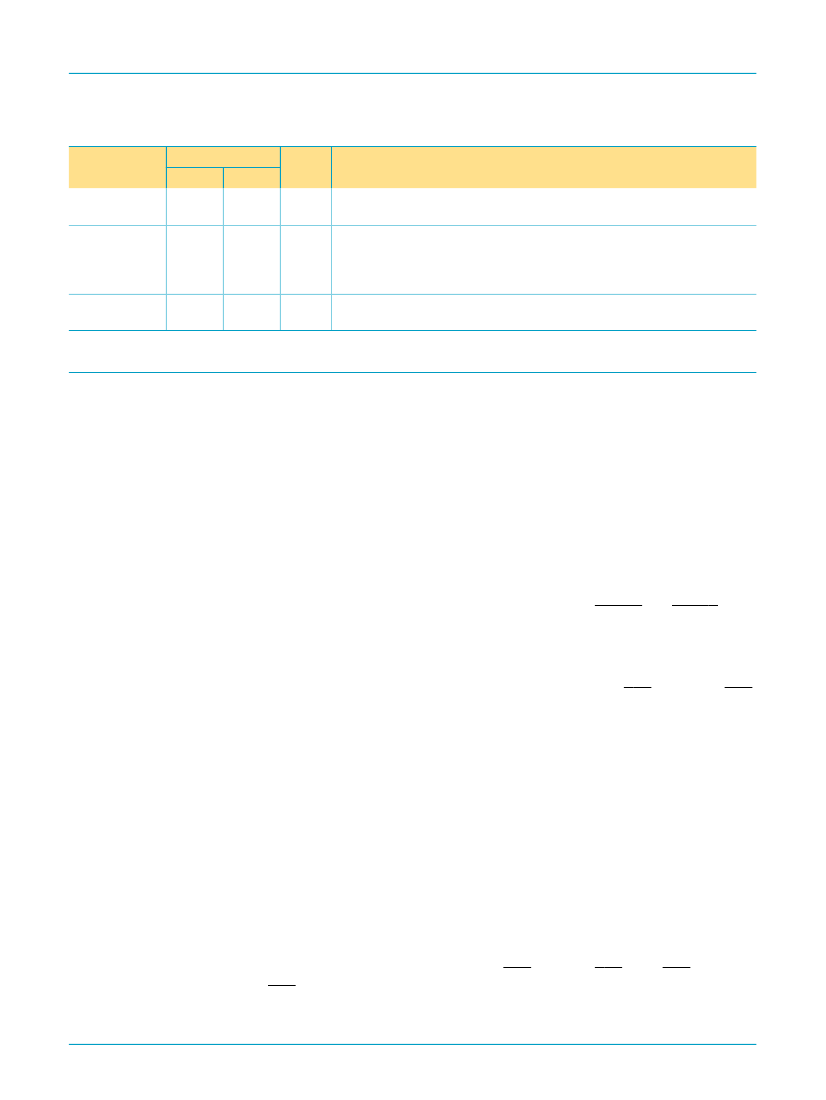
Table 2:
Symbol
V
CC
XTAL1
Pin description
鈥ontinued
Pin
LQFP80 PLCC68
6, 46, 66 13, 47,
64
31
35
I
I
Power supply input.
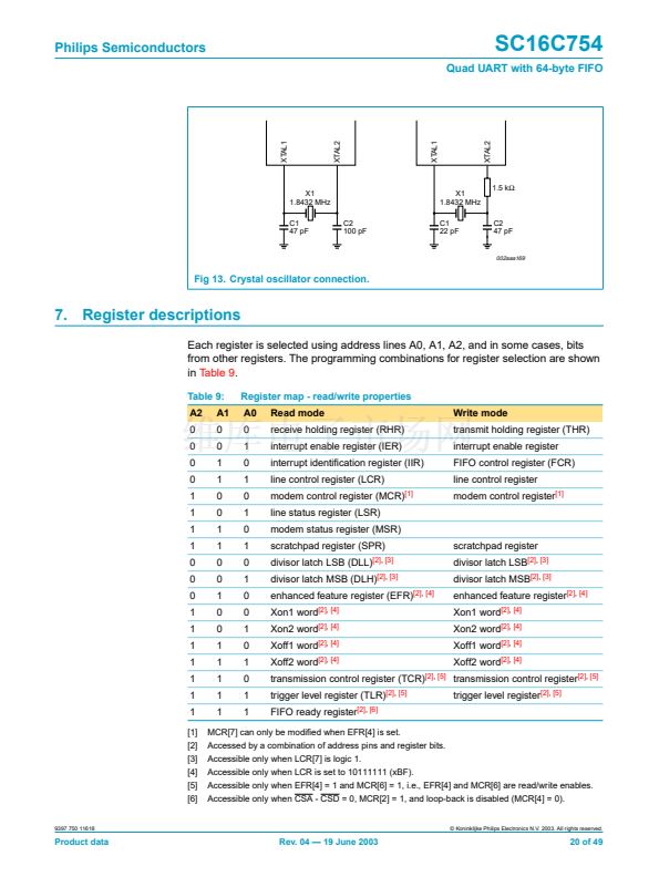
Crystal or external clock input.
Functions as a crystal input or as an
external clock input. A crystal can be connected between XTAL1 and XTAL2
to form an internal oscillator circuit (see
Figure 13).
Alternatively, an
external clock can be connected to this pin to provide custom data rates.
Output of the crystal oscillator or buffered clock.
(See also XTAL1.)
XTAL2 is used as a crystal oscillator output or a buffered clock output.
Type
Description
XTAL2
32
36
O
6. Functional description
The SC16C754 UART is pin-compatible with the SC16C554 and SC16C654 UARTs.
It provides more enhanced features. All additional features are provided through a
special enhanced feature register.
The UART will perform serial-to-parallel conversion on data characters received from
peripheral devices or modems, and parallel-to-parallel conversion on data characters
transmitted by the processor. The complete status of each channel of the SC16C754
UART can be read at any time during functional operation by the processor.
The SC16C754 can be placed in an alternate mode (FIFO mode) relieving the
processor of excessive software overhead by buffering received/transmitted
characters. Both the receiver and transmitter FIFOs can store up to 64 bytes
(including three additional bits of error status per byte for the receiver FIFO) and have
selectable or programmable trigger levels. Primary outputs RXRDY and TXRDY allow
signalling of DMA transfers.
The SC16C754 has selectable hardware 铿俹w control and software 铿俹w control.
Hardware 铿俹w control signi铿乧antly reduces software overhead and increases system
ef铿乧iency by automatically controlling serial data 铿俹w using the RTS output and CTS
input signals. Software 铿俹w control automatically controls data 铿俹w by using
programmable Xon/Xoff characters.
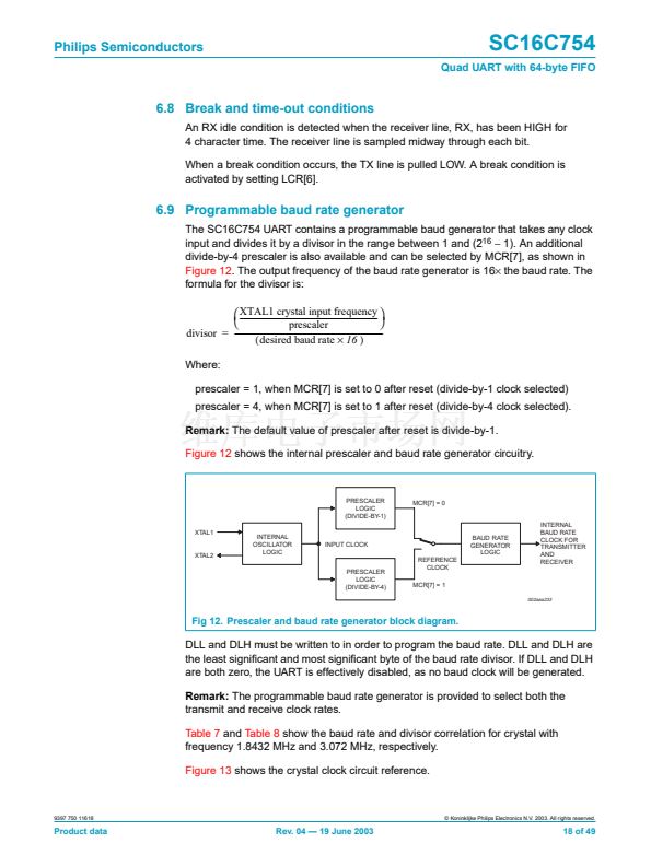
The UART includes a programmable baud rate generator that can divide the timing
reference clock input by a divisor between 1 and (2
16
鈭?/div>
1).
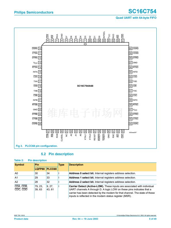
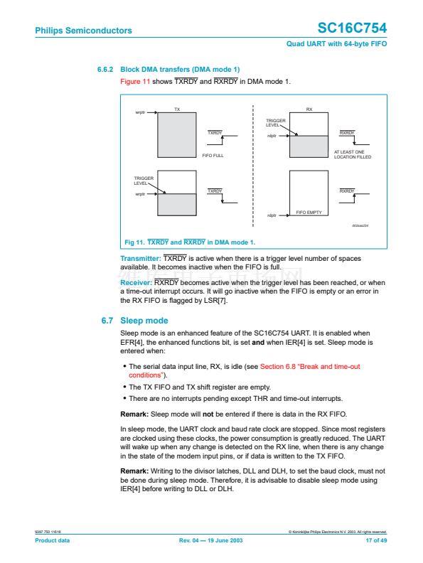
6.1 Trigger levels
The SC16C754 provides independent selectable and programmable trigger levels for
both receiver and transmitter DMA and interrupt generation. After reset, both
transmitter and receiver FIFOs are disabled and so, in effect, the trigger level is the
default value of one byte. The selectable trigger levels are available via the FCR. The
programmable trigger levels are available via the TLR.
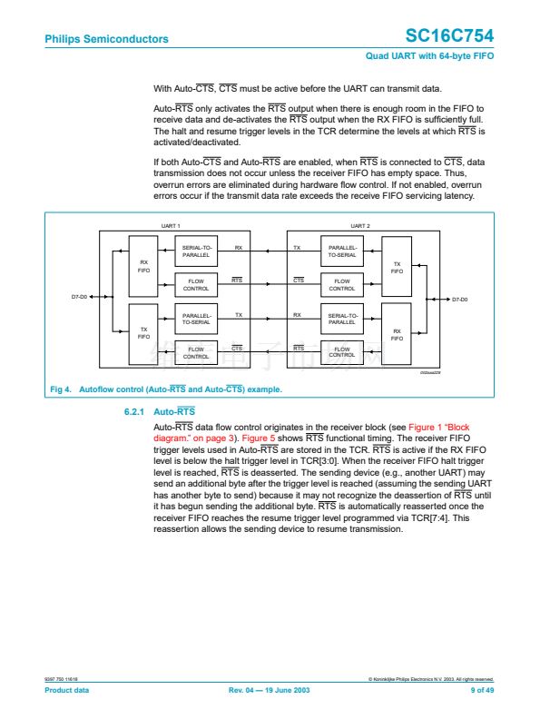
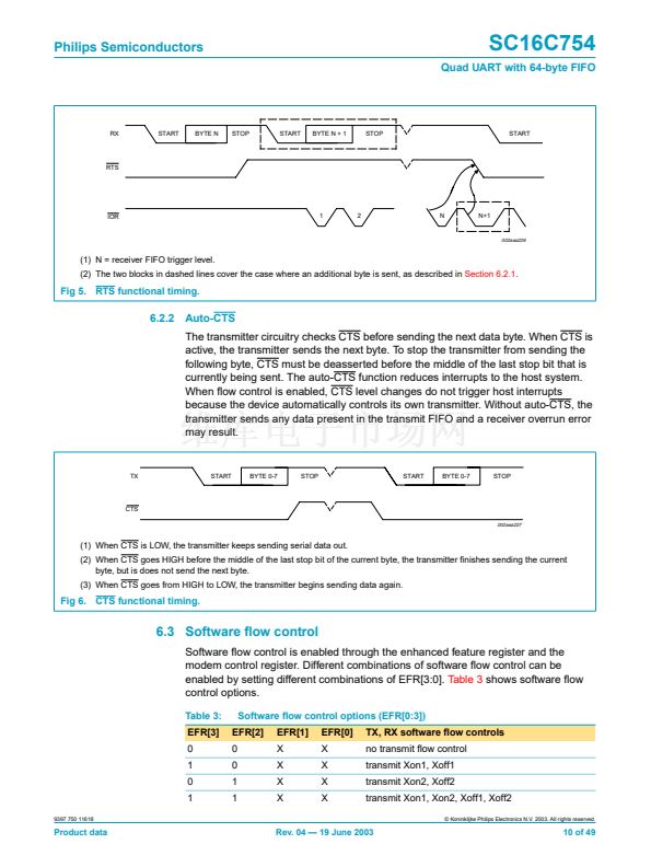
6.2 Hardware 铿俹w control
Hardware 铿俹w control is comprised of Auto-CTS and Auto-RTS. Auto-CTS and
Auto-RTS can be enabled/disabled independently by programming EFR[7:6].
9397 750 11618
漏 Koninklijke Philips Electronics N.V. 2003. All rights reserved.
Product data
Rev. 04 鈥?19 June 2003
8 of 49


 1
1
 2
2
 3
3
 4
4
 5
5
 6
6
 7
7
 8
8
 9
9
 10
10
 11
11
 12
12
 13
13
 14
14
 15
15
 16
16
 17
17
 18
18
 19
19
 20
20
 21
21
 22
22
 23
23
 24
24
 25
25
 26
26
 27
27
 28
28
 29
29
 30
30
 31
31
 32
32
 33
33
 34
34
 35
35
 36
36
 37
37
 38
38
 39
39
 40
40
 41
41
 42
42
 43
43
 44
44
 45
45
 46
46
 47
47
 48
48
 49
49
