Sleep mode.
Logic 0 = Disable sleep mode (normal default condition).
Logic 1 = Enable sleep mode. See
Section 6.7 鈥淪leep mode鈥?/div>
for details.
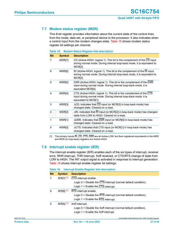
Table 16:
Bit
4
Symbol
IER[4]
[1]
3
IER[3]
Modem Status Interrupt.
Logic 0 = Disable the modem status register interrupt (normal default
condition).
Logic 1 = Enable the modem status register interrupt.
2
IER[2]
Receive Line Status interrupt.
Logic 0 = Disable the receiver line status interrupt (normal default
condition).
Logic 1 = Enable the receiver line status interrupt.
1
IER[1]
Transmit Holding Register interrupt.
Logic 0 = Disable the THR interrupt (normal default condition).
Logic 1 = Enable the THR interrupt.
0
IER[0]
Receive Holding Register interrupt.
Logic 0 = Disable the RHR interrupt (normal default condition).
Logic 1 = Enable the RHR interrupt.
[1]
IER[7:4] can only be modi铿乪d if EFR[4] is set, i.e., EFR[4] is a write enable. Re-enabling IER[1] will
not cause a new interrupt if the THR is below the threshold.
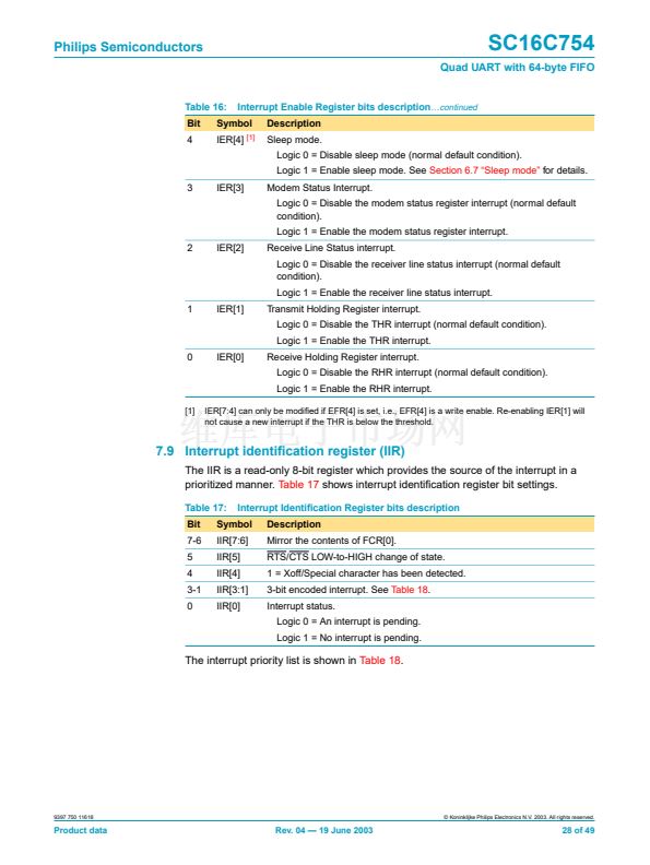
7.9 Interrupt identi铿乧ation register (IIR)
The IIR is a read-only 8-bit register which provides the source of the interrupt in a
prioritized manner.
Table 17
shows interrupt identi铿乧ation register bit settings.
Table 17:
Bit
7-6
5
4
3-1
0
Interrupt Identi铿乧ation Register bits description
Description
Mirror the contents of FCR[0].
RTS/CTS LOW-to-HIGH change of state.
1 = Xoff/Special character has been detected.
3-bit encoded interrupt. See
Table 18.
Interrupt status.
Logic 0 = An interrupt is pending.
Logic 1 = No interrupt is pending.
Symbol
IIR[7:6]
IIR[5]
IIR[4]
IIR[3:1]
IIR[0]
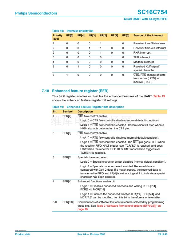
The interrupt priority list is shown in
Table 18.
9397 750 11618
漏 Koninklijke Philips Electronics N.V. 2003. All rights reserved.
Product data
Rev. 04 鈥?19 June 2003
28 of 49


 1
1
 2
2
 3
3
 4
4
 5
5
 6
6
 7
7
 8
8
 9
9
 10
10
 11
11
 12
12
 13
13
 14
14
 15
15
 16
16
 17
17
 18
18
 19
19
 20
20
 21
21
 22
22
 23
23
 24
24
 25
25
 26
26
 27
27
 28
28
 29
29
 30
30
 31
31
 32
32
 33
33
 34
34
 35
35
 36
36
 37
37
 38
38
 39
39
 40
40
 41
41
 42
42
 43
43
 44
44
 45
45
 46
46
 47
47
 48
48
 49
49
