Philips Semiconductors
SC16C754
Quad UART with 64-byte FIFO
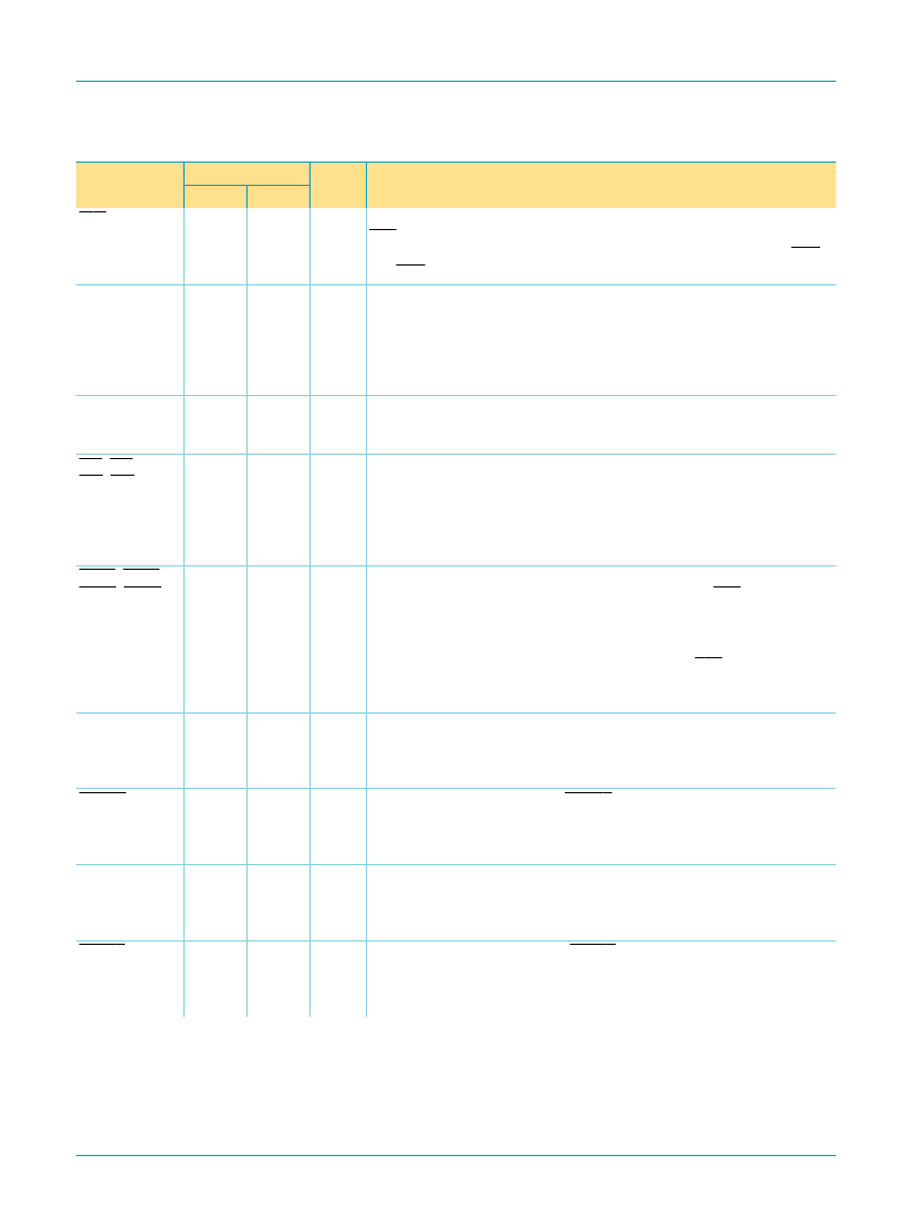
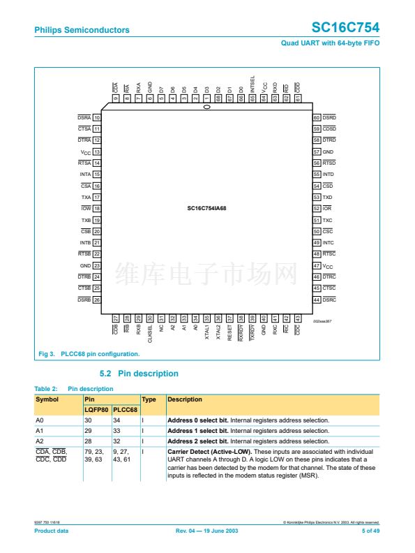
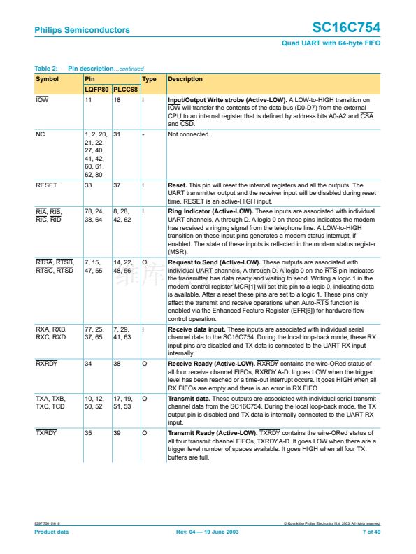
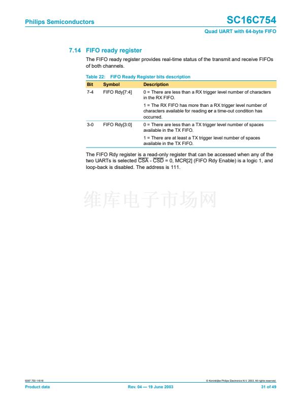
Table 2:
Symbol
IOW
Pin description
鈥ontinued
Pin
LQFP80 PLCC68
11
18
I
Input/Output Write strobe (Active-LOW).
A LOW-to-HIGH transition on
IOW will transfer the contents of the data bus (D0-D7) from the external
CPU to an internal register that is de铿乶ed by address bits A0-A2 and CSA
and CSD.
Not connected.
Type
Description
NC
1, 2, 20, 31
21, 22,
27, 40,
41, 42,
60, 61,
62, 80
33
37
-
RESET
I
Reset.
This pin will reset the internal registers and all the outputs. The
UART transmitter output and the receiver input will be disabled during reset
time. RESET is an active-HIGH input.
Ring Indicator (Active-LOW).
These inputs are associated with individual
UART channels, A through D. A logic 0 on these pins indicates the modem
has received a ringing signal from the telephone line. A LOW-to-HIGH
transition on these input pins generates a modem status interrupt, if
enabled. The state of these inputs is re铿俥cted in the modem status register
(MSR).
Request to Send (Active-LOW).
These outputs are associated with
individual UART channels, A through D. A logic 0 on the RTS pin indicates
the transmitter has data ready and waiting to send. Writing a logic 1 in the
modem control register MCR[1] will set this pin to a logic 0, indicating data
is available. After a reset these pins are set to a logic 1. These pins only
affect the transmit and receive operations when Auto-RTS function is
enabled via the Enhanced Feature Register (EFR[6]) for hardware 铿俹w
control operation.
Receive data input.
These inputs are associated with individual serial
channel data to the SC16C754. During the local loop-back mode, these RX
input pins are disabled and TX data is connected to the UART RX input
internally.
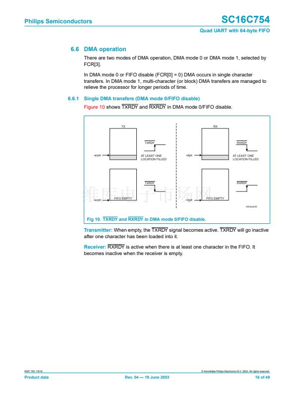
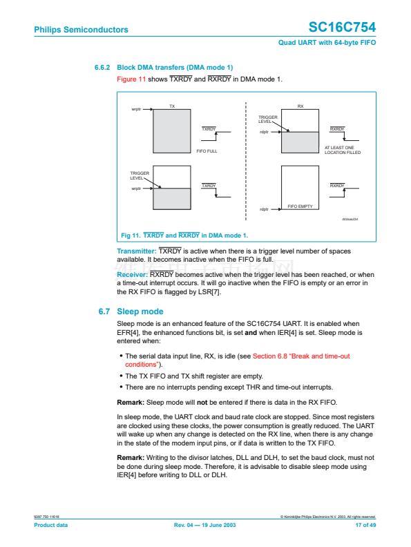
Receive Ready (Active-LOW).
RXRDY contains the wire-ORed status of
all four receive channel FIFOs, RXRDY A-D. It goes LOW when the trigger
level has been reached or a time-out interrupt occurs. It goes HIGH when all
RX FIFOs are empty and there is an error in RX FIFO.
Transmit data.
These outputs are associated with individual serial transmit
channel data from the SC16C754. During the local loop-back mode, the TX
output pin is disabled and TX data is internally connected to the UART RX
input.
Transmit Ready (Active-LOW).
TXRDY contains the wire-ORed status of
all four transmit channel FIFOs, TXRDY A-D. It goes LOW when there are a
trigger level number of spaces available. It goes HIGH when all four TX
buffers are full.
RIA, RIB,
RIC, RID
78, 24,
38, 64
8, 28,
42, 62
I
RTSA, RTSB,
RTSC, RTSD
7, 15,
47, 55
14, 22,
48, 56
O
RXA, RXB,
RXC, RXD
77, 25,
37, 65
7, 29,
41, 63
I
RXRDY
34
38
O
TXA, TXB,
TXC, TCD
10, 12,
50, 52
17, 19,
51, 53
O
TXRDY
35
39
O
9397 750 11618
漏 Koninklijke Philips Electronics N.V. 2003. All rights reserved.
Product data
Rev. 04 鈥?19 June 2003
7 of 49


 1
1
 2
2
 3
3
 4
4
 5
5
 6
6
 7
7
 8
8
 9
9
 10
10
 11
11
 12
12
 13
13
 14
14
 15
15
 16
16
 17
17
 18
18
 19
19
 20
20
 21
21
 22
22
 23
23
 24
24
 25
25
 26
26
 27
27
 28
28
 29
29
 30
30
 31
31
 32
32
 33
33
 34
34
 35
35
 36
36
 37
37
 38
38
 39
39
 40
40
 41
41
 42
42
 43
43
 44
44
 45
45
 46
46
 47
47
 48
48
 49
49
