Philips Semiconductors
SC16C754
Quad UART with 64-byte FIFO
7.11 Divisor latches (DLL, DLH)
These are two 8-bit registers which store the 16-bit divisor for generation of the baud
clock in the baud rate generator. DLH stores the most signi铿乧ant part of the divisor.
DLL stores the least signi铿乧ant part of the divisor.
Note that DLL and DLH can only be written to before sleep mode is enabled, i.e.,
before IER[4] is set.
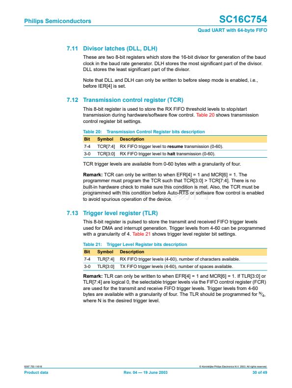
7.12 Transmission control register (TCR)
This 8-bit register is used to store the RX FIFO threshold levels to stop/start
transmission during hardware/software 铿俹w control.
Table 20
shows transmission
control register bit settings.
Table 20:
Bit
7-4
3-0
Transmission Control Register bits description
Description
RX FIFO trigger level to
resume
transmission (0-60).
RX FIFO trigger level to
halt
transmission (0-60).
Symbol
TCR[7:4]
TCR[3:0]
TCR trigger levels are available from 0-60 bytes with a granularity of four.
Remark:
TCR can only be written to when EFR[4] = 1 and MCR[6] = 1. The
programmer must program the TCR such that TCR[3:0] > TCR[7:4]. There is no
built-in hardware check to make sure this condition is met. Also, the TCR must be
programmed with this condition before Auto-RTS or software 铿俹w control is enabled
to avoid spurious operation of the device.
7.13 Trigger level register (TLR)
This 8-bit register is pulsed to store the transmit and received FIFO trigger levels
used for DMA and interrupt generation. Trigger levels from 4-60 can be programmed
with a granularity of 4.
Table 21
shows trigger level register bit settings.
Table 21:
Bit
7-4
3-0
Trigger Level Register bits description
Description
RX FIFO trigger levels (4-60), number of characters available.
TX FIFO trigger levels (4-60), number of spaces available.
Symbol
TLR[7:4]
TLR[3:0]
Remark:
TLR can only be written to when EFR[4] = 1 and MCR[6] = 1. If TLR[3:0] or
TLR[7:4] are logical 0, the selectable trigger levels via the FIFO control register (FCR)
are used for the transmit and receive FIFO trigger levels. Trigger levels from 4-60
bytes are available with a granularity of four. The TLR should be programmed for
N
鈦?/div>
4
,
where N is the desired trigger level.
9397 750 11618
漏 Koninklijke Philips Electronics N.V. 2003. All rights reserved.
Product data
Rev. 04 鈥?19 June 2003
30 of 49


 1
1
 2
2
 3
3
 4
4
 5
5
 6
6
 7
7
 8
8
 9
9
 10
10
 11
11
 12
12
 13
13
 14
14
 15
15
 16
16
 17
17
 18
18
 19
19
 20
20
 21
21
 22
22
 23
23
 24
24
 25
25
 26
26
 27
27
 28
28
 29
29
 30
30
 31
31
 32
32
 33
33
 34
34
 35
35
 36
36
 37
37
 38
38
 39
39
 40
40
 41
41
 42
42
 43
43
 44
44
 45
45
 46
46
 47
47
 48
48
 49
49
