DS26502 T1/E1/J1/64KCC BITS Element
8. T1 FRAMER/FORMATTER CONTROL REGISTERS
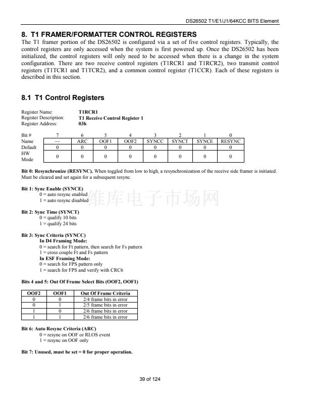
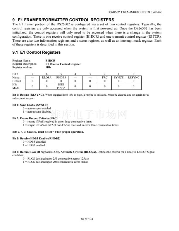
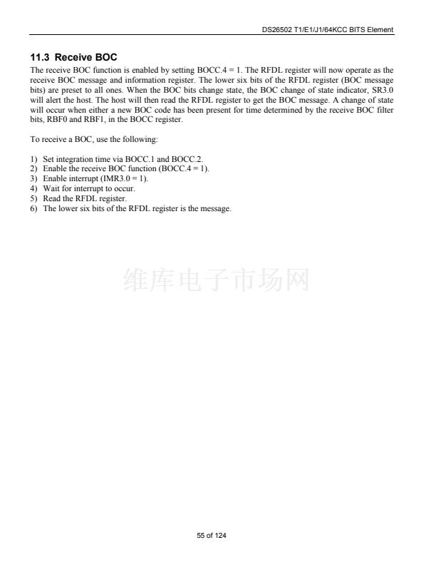
The T1 framer portion of the DS26502 is configured via a set of five control registers. Typically, the
control registers are only accessed when the system is first powered up. Once the DS26502 has been
initialized, the control registers will only need to be accessed when there is a change in the system
configuration. There are two receive control registers (T1RCR1 and T1RCR2), two transmit control
registers (T1TCR1 and T1TCR2), and a common control register (T1CCR). Each of these registers is
described in this section.
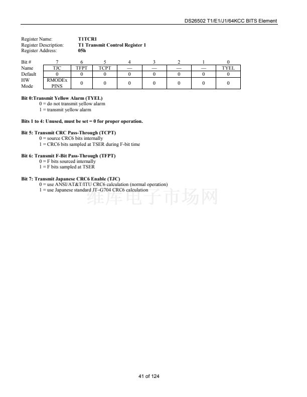
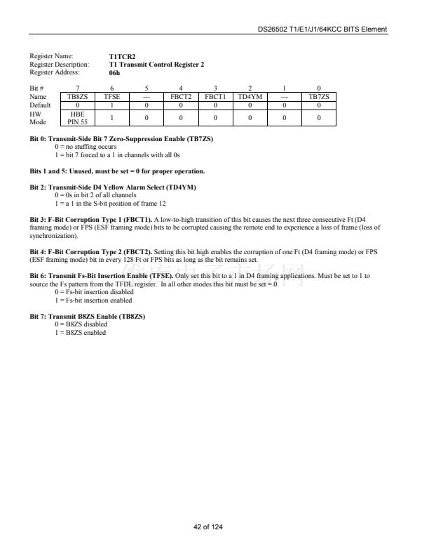
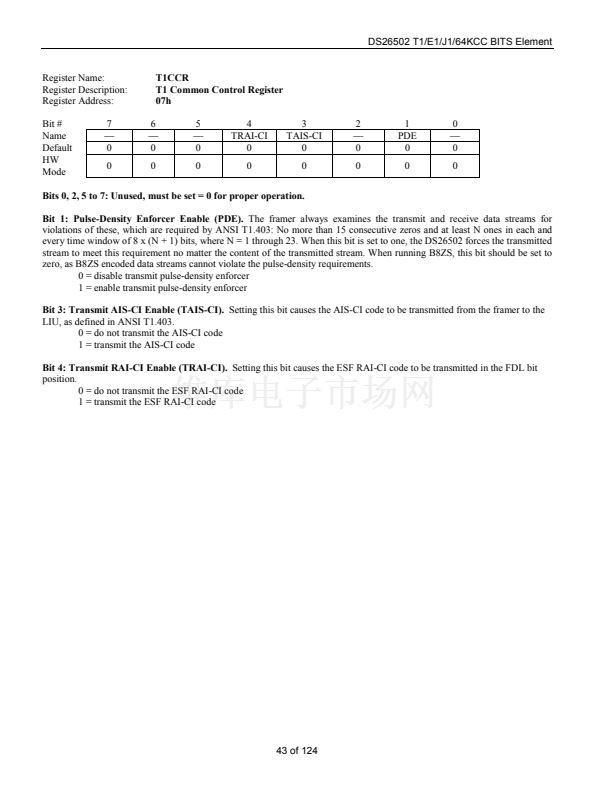
8.1 T1 Control Registers
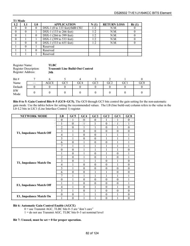
Register Name:
Register Description:
Register Address:
Bit #
Name
Default
HW
Mode
7
鈥?/div>
0
0
T1RCR1
T1 Receive Control Register 1
03h
6
ARC
0
0
5
OOF1
0
0
4
OOF2
0
0
3
SYNCC
0
0
2
SYNCT
0
0
1
SYNCE
0
0
0
RESYNC
0
0
Bit 0: Resynchronize (RESYNC).
When toggled from low to high, a resynchronization of the receive side framer is initiated.
Must be cleared and set again for a subsequent resync.
Bit 1: Sync Enable (SYNCE)
0 = auto resync enabled
1 = auto resync disabled
Bit 2: Sync Time (SYNCT)
0 = qualify 10 bits
1 = qualify 24 bits
Bit 3: Sync Criteria (SYNCC)
In D4 Framing Mode:
0 = search for Ft pattern, then search for Fs pattern
1 = cross couple Ft and Fs pattern
In ESF Framing Mode:
0 = search for FPS pattern only
1 = search for FPS and verify with CRC6
Bits 4 and 5: Out Of Frame Select Bits (OOF2, OOF1)
OOF2
0
0
1
1
OOF1
0
1
0
1
Out Of Frame Criteria
2/4 frame bits in error
2/5 frame bits in error
2/6 frame bits in error
2/6 frame bits in error
Bit 6: Auto Resync Criteria (ARC)
0 = resync on OOF or RLOS event
1 = resync on OOF only
Bit 7: Unused, must be set = 0 for proper operation.
39 of 124


 1
1
 2
2
 3
3
 4
4
 5
5
 6
6
 7
7
 8
8
 9
9
 10
10
 11
11
 12
12
 13
13
 14
14
 15
15
 16
16
 17
17
 18
18
 19
19
 20
20
 21
21
 22
22
 23
23
 24
24
 25
25
 26
26
 27
27
 28
28
 29
29
 30
30
 31
31
 32
32
 33
33
 34
34
 35
35
 36
36
 37
37
 38
38
 39
39
 40
40
 41
41
 42
42
 43
43
 44
44
 45
45
 46
46
 47
47
 48
48
 49
49
 50
50
 51
51
 52
52
 53
53
 54
54
 55
55
 56
56
 57
57
 58
58
 59
59
 60
60
 61
61
 62
62
 63
63
 64
64
 65
65
 66
66
 67
67
 68
68
 69
69
 70
70
 71
71
 72
72
 73
73
 74
74
 75
75
 76
76
 77
77
 78
78
 79
79
 80
80
 81
81
 82
82
 83
83
 84
84
 85
85
 86
86
 87
87
 88
88
 89
89
 90
90
 91
91
 92
92
 93
93
 94
94
 95
95
 96
96
 97
97
 98
98
 99
99
 100
100
 101
101
 102
102
 103
103
 104
104
 105
105
 106
106
 107
107
 108
108
 109
109
 110
110
 111
111
 112
112
 113
113
 114
114
 115
115
 116
116
 117
117
 118
118
 119
119
 120
120
 121
121
 122
122
 123
123
 124
124
