DS26502 T1/E1/J1/64KCC BITS Element
13.1 LIU Operation
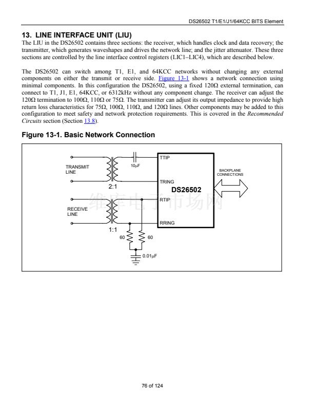
The LIU interfaces the T1, E1, 64KCC, and 6312kHz signals to the various types of network media
through coupling transformers. The LIU transmit and receive functions are independent. For example, the
receiver can be in T1 mode while the transmitter is in E1 mode. The 6312kHz transmission is an
exception to the other modes. For transmission, 6312kHz is only available as a 0 to 3.3V signal on the
TCLKO pin. It is not output to the TTIP and TRING pins for coupling to twisted pair. Because the G.703
specifications of the transmit pulse shape for Japanese 6312kHz are unclear, the user can externally filter
this signal to generate a sine wave type of signal. However, on the receive side, 6312kHz can be input
through the receive transformer to the RTIP and RRING pins.
13.2 LIU Receiver
The analog AMI/HDB3 E1 waveform, AMI/B8ZS T1 waveform, or AMI 64KCC waveform is
transformer-coupled into the RTIP and RRING pins of the DS26502. The user has the option to use
internal termination, software-selectable for 75/100/110/120W applications, or external termination. The
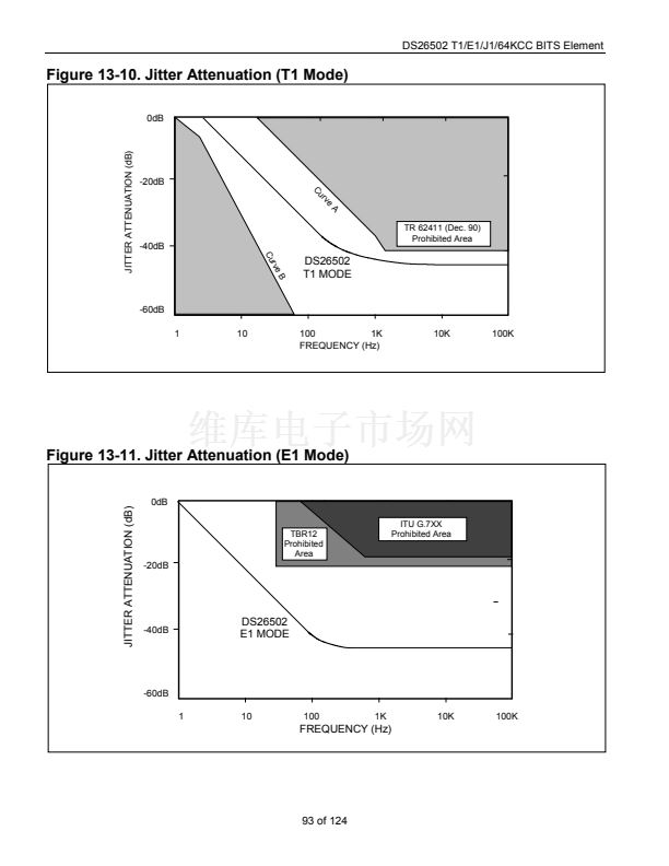
LIU recovers clock and data from the analog signal and passes it through the jitter attenuation mux.
(Note: The jitter attenuator is only available in T1 or E1 mode.) The DS26502 contains an active filter
that reconstructs the analog-received signal for the nonlinear losses that occur in long-haul T1 and E1
transmission. The receiver is configurable for various T1 and E1 monitor applications. The device has a
usable receive sensitivity of 0dB to 鈥?3dB for E1 and 0dB to 鈥?6dB for T1, which allows the device to
operate on 0.63mm (22AWG) cables up to 2.5km (E1) and 6000ft (T1) in length.
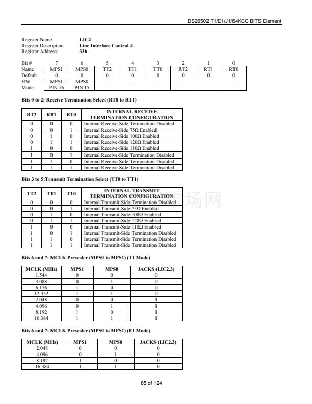
The DS26502鈥檚 LIU is designed to be fully software selectable for E1 and T1 without the need to change
any external resistors for the receive-side. The receiver will allow the user to configure the DS26502 for
75鈩? 100鈩? 110鈩? or 120鈩?receive termination by setting the RT0(LIC4.0), RT1(LIC4.1), and
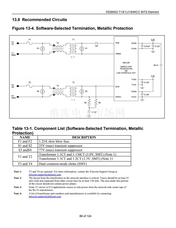
RT2(LIC4.2). When using the internal termination feature, the resistors labeled R in
Figure 13-4
should
be 60鈩?each. If external termination is used, RT0, RT1, and RT2 should be set to zero and the resistors
labeled R in
Figure 13-4
will need to be 37.5鈩? 50鈩? 55鈩? or 60鈩?each, depending on the required
termination.
There are two ranges of receive sensitivity for T1 and E1, which is selectable by the user. The EGL bit of
LIC1 (LIC1.4) selects the full or limited sensitivity.
Normally, the clock that is output at the RCLK pin is the recovered clock from the waveform presented at
the RTIP and RRING inputs. If the jitter attenuator is placed in the receive path (as is the case in most
applications), the jitter attenuator restores the RCLK to an approximate 50% duty cycle. If the jitter
attenuator is either placed in the transmit path or is disabled, the RCLK output can exhibit slightly shorter
high cycles of the clock. This is due to the highly over-sampled digital clock recovery circuitry. See the
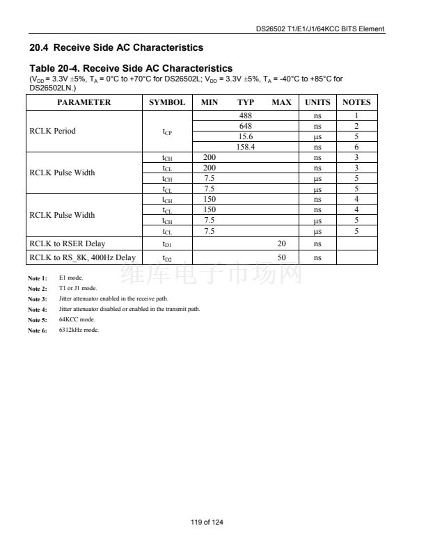
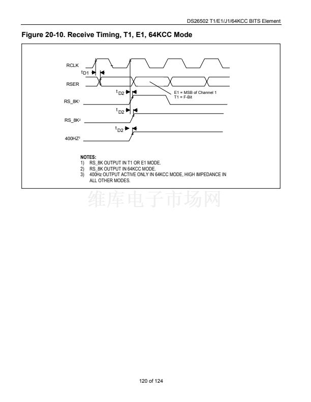
Receive AC Timing Characteristics
section for more details. When no signal is present at RTIP and
RRING, a receive loss of signal (RLOS) condition will occur and the signal at RCLK will be derived
from the scaled signal present on the MCLK pin JACLK.
13.2.1 Receive Level Indicator
The DS26502 will report the signal strength at RTIP and RRING in 2.5dB increments via RL3-RL0
located in the Information Register 1 (INFO1). This feature is helpful when trouble shooting line
performance problems.
77 of 124


 1
1
 2
2
 3
3
 4
4
 5
5
 6
6
 7
7
 8
8
 9
9
 10
10
 11
11
 12
12
 13
13
 14
14
 15
15
 16
16
 17
17
 18
18
 19
19
 20
20
 21
21
 22
22
 23
23
 24
24
 25
25
 26
26
 27
27
 28
28
 29
29
 30
30
 31
31
 32
32
 33
33
 34
34
 35
35
 36
36
 37
37
 38
38
 39
39
 40
40
 41
41
 42
42
 43
43
 44
44
 45
45
 46
46
 47
47
 48
48
 49
49
 50
50
 51
51
 52
52
 53
53
 54
54
 55
55
 56
56
 57
57
 58
58
 59
59
 60
60
 61
61
 62
62
 63
63
 64
64
 65
65
 66
66
 67
67
 68
68
 69
69
 70
70
 71
71
 72
72
 73
73
 74
74
 75
75
 76
76
 77
77
 78
78
 79
79
 80
80
 81
81
 82
82
 83
83
 84
84
 85
85
 86
86
 87
87
 88
88
 89
89
 90
90
 91
91
 92
92
 93
93
 94
94
 95
95
 96
96
 97
97
 98
98
 99
99
 100
100
 101
101
 102
102
 103
103
 104
104
 105
105
 106
106
 107
107
 108
108
 109
109
 110
110
 111
111
 112
112
 113
113
 114
114
 115
115
 116
116
 117
117
 118
118
 119
119
 120
120
 121
121
 122
122
 123
123
 124
124
