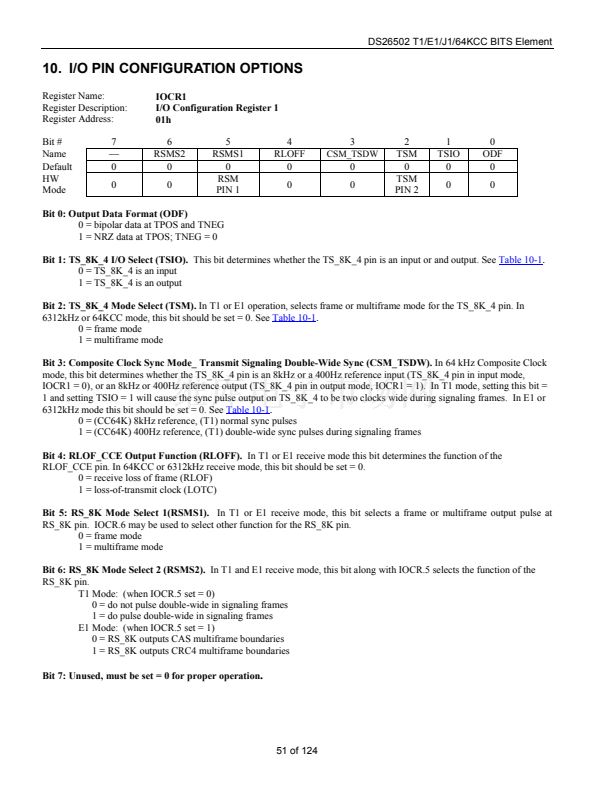
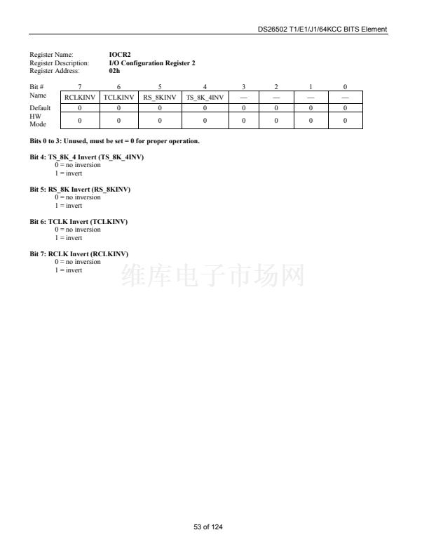
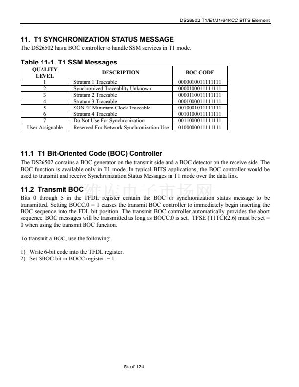
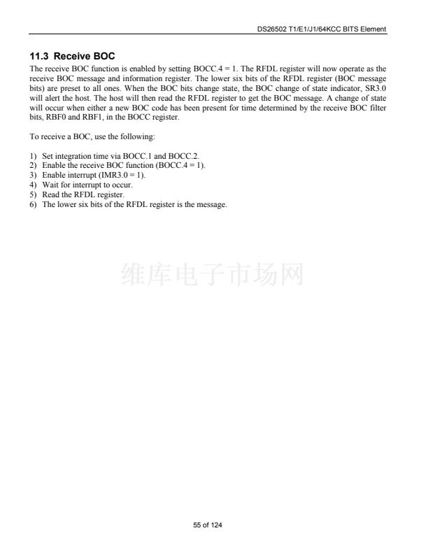
DS26502 T1/E1/J1/64KCC BITS Element
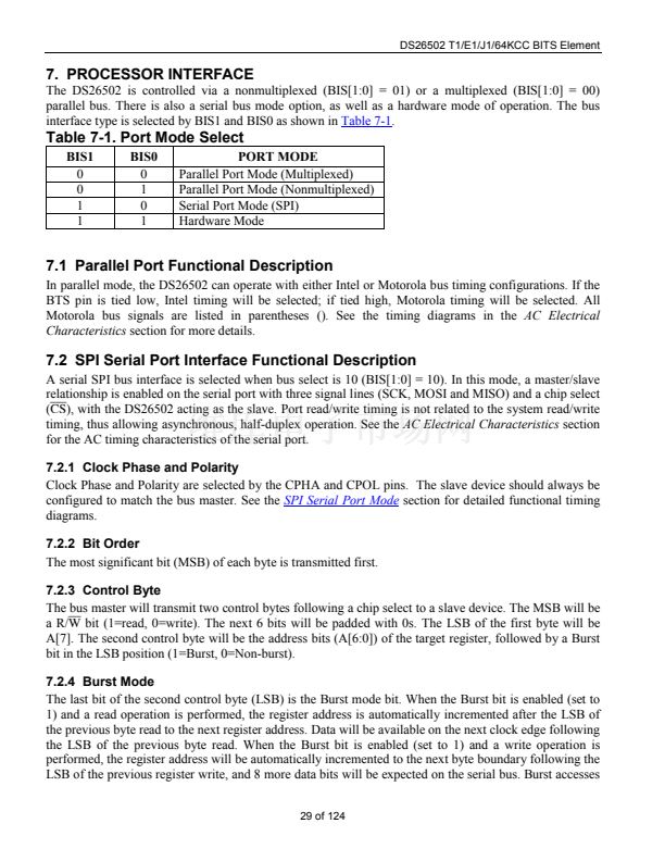
13.8 Recommended Circuits
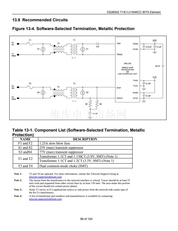
Figure 13-4. Software-Selected Termination, Metallic Protection
Table 13-1. Component List (Software-Selected Termination, Metallic
Protection)
NAME
F1 and F2
S1 and S2
S3 andS4
T1 and T2
T3 and T4
Note 1:
Note 2:
Note 3:
Note 4:
DESCRIPTION
1.25A slow blow fuse
25V (max) transient suppressor
77V (max) transient suppressor
Transformer 1:1CT and 1:136CT (5.0V, SMT) (Note 1)
Transformer 1:1CT and 1:2CT (3.3V, SMT) (Note 1)
Dual common-mode choke (SMT)
T3 and T4 are optional. For more information, contact the Telecom Support Group at
telecom.support@dalsemi.com.
The layout from the transformers to the network interface is critical. Traces should be at least 25
mils wide and separated from other circuit lines by at least 150 mils. The area under this portion
of the circuit should not contain power planes.
Some T1 (never in E1) applications source or sink power from the network-side center taps of
the Rx/Tx transformers.
A list of transformer part numbers and manufacturers is available by contacting
telecom.support@dalsemi.com.
89 of 124


 1
1
 2
2
 3
3
 4
4
 5
5
 6
6
 7
7
 8
8
 9
9
 10
10
 11
11
 12
12
 13
13
 14
14
 15
15
 16
16
 17
17
 18
18
 19
19
 20
20
 21
21
 22
22
 23
23
 24
24
 25
25
 26
26
 27
27
 28
28
 29
29
 30
30
 31
31
 32
32
 33
33
 34
34
 35
35
 36
36
 37
37
 38
38
 39
39
 40
40
 41
41
 42
42
 43
43
 44
44
 45
45
 46
46
 47
47
 48
48
 49
49
 50
50
 51
51
 52
52
 53
53
 54
54
 55
55
 56
56
 57
57
 58
58
 59
59
 60
60
 61
61
 62
62
 63
63
 64
64
 65
65
 66
66
 67
67
 68
68
 69
69
 70
70
 71
71
 72
72
 73
73
 74
74
 75
75
 76
76
 77
77
 78
78
 79
79
 80
80
 81
81
 82
82
 83
83
 84
84
 85
85
 86
86
 87
87
 88
88
 89
89
 90
90
 91
91
 92
92
 93
93
 94
94
 95
95
 96
96
 97
97
 98
98
 99
99
 100
100
 101
101
 102
102
 103
103
 104
104
 105
105
 106
106
 107
107
 108
108
 109
109
 110
110
 111
111
 112
112
 113
113
 114
114
 115
115
 116
116
 117
117
 118
118
 119
119
 120
120
 121
121
 122
122
 123
123
 124
124
