10. I/O PIN CONFIGURATION OPTIONS
鈥?/div>
0
0
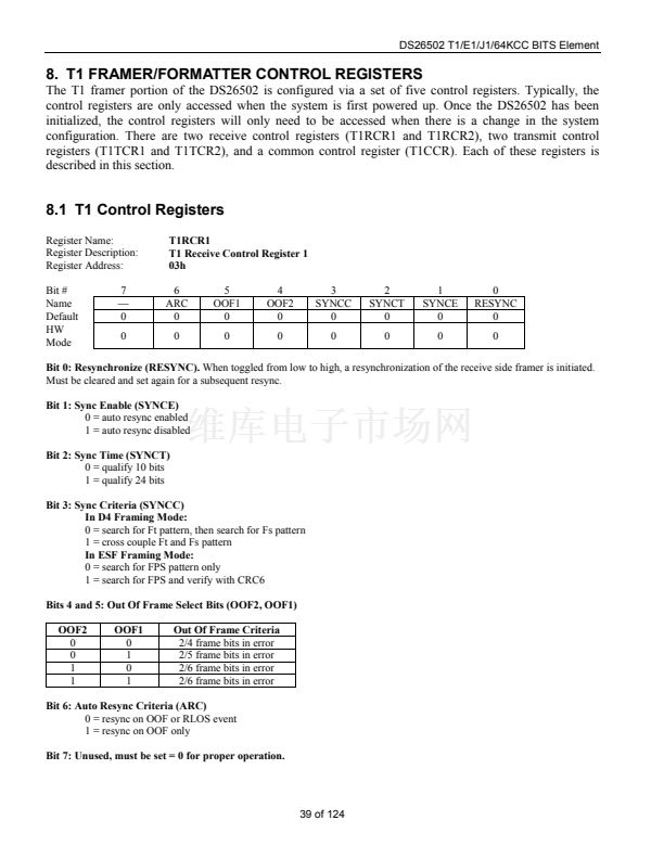
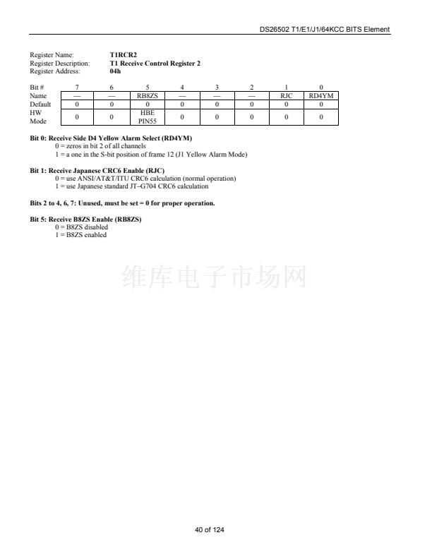
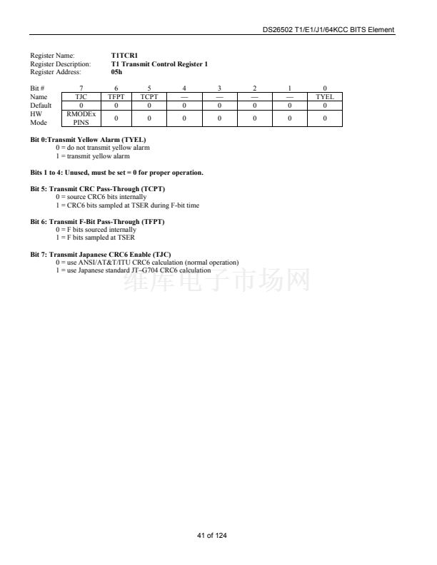
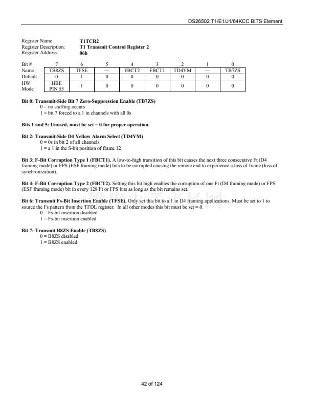
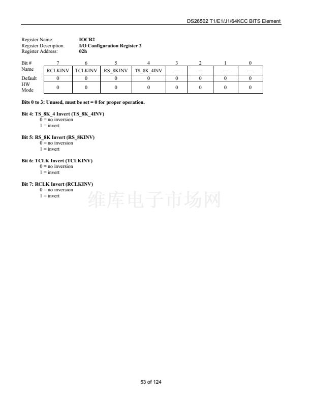
IOCR1
I/O Configuration Register 1
01h
6
RSMS2
0
0
5
RSMS1
0
RSM
PIN 1
4
RLOFF
0
0
3
CSM_TSDW
0
0
2
TSM
0
TSM
PIN 2
1
TSIO
0
0
0
ODF
0
0
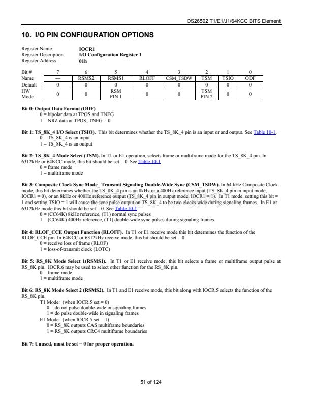
Bit 0: Output Data Format (ODF)
0 = bipolar data at TPOS and TNEG
1 = NRZ data at TPOS; TNEG = 0
Bit 1: TS_8K_4 I/O Select (TSIO).
This bit determines whether the TS_8K_4 pin is an input or and output. See
Table 10-1.
0 = TS_8K_4 is an input
1 = TS_8K_4 is an output
Bit 2: TS_8K_4 Mode Select (TSM).
In T1 or E1 operation, selects frame or multiframe mode for the TS_8K_4 pin. In
6312kHz or 64KCC mode, this bit should be set = 0. See
Table 10-1.
0 = frame mode
1 = multiframe mode
Bit 3: Composite Clock Sync Mode_ Transmit Signaling Double-Wide Sync (CSM_TSDW).
In 64 kHz Composite Clock
mode, this bit determines whether the TS_8K_4 pin is an 8kHz or a 400Hz reference input (TS_8K_4 pin in input mode,
IOCR1 = 0), or an 8kHz or 400Hz reference output (TS_8K_4 pin in output mode, IOCR1 = 1). In T1 mode, setting this bit =
1 and setting TSIO = 1 will cause the sync pulse output on TS_8K_4 to be two clocks wide during signaling frames. In E1 or
6312kHz mode this bit should be set = 0. See
Table 10-1.
0 = (CC64K) 8kHz reference, (T1) normal sync pulses
1 = (CC64K) 400Hz reference, (T1) double-wide sync pulses during signaling frames
Bit 4: RLOF_CCE Output Function (RLOFF).
In T1 or E1 receive mode this bit determines the function of the
RLOF_CCE pin. In 64KCC or 6312kHz receive mode, this bit should be set = 0.
0 = receive loss of frame (RLOF)
1 = loss-of-transmit clock (LOTC)
Bit 5: RS_8K Mode Select 1(RSMS1).
In T1 or E1 receive mode, this bit selects a frame or multiframe output pulse at
RS_8K pin. IOCR.6 may be used to select other function for the RS_8K pin.
0 = frame mode
1 = multiframe mode
Bit 6: RS_8K Mode Select 2 (RSMS2).
In T1 and E1 receive mode, this bit along with IOCR.5 selects the function of the
RS_8K pin.
T1 Mode: (when IOCR.5 set = 0)
0 = do not pulse double-wide in signaling frames
1 = do pulse double-wide in signaling frames
E1 Mode: (when IOCR.5 set = 1)
0 = RS_8K outputs CAS multiframe boundaries
1 = RS_8K outputs CRC4 multiframe boundaries
Bit 7: Unused, must be set = 0 for proper operation
.
51 of 124


 1
1
 2
2
 3
3
 4
4
 5
5
 6
6
 7
7
 8
8
 9
9
 10
10
 11
11
 12
12
 13
13
 14
14
 15
15
 16
16
 17
17
 18
18
 19
19
 20
20
 21
21
 22
22
 23
23
 24
24
 25
25
 26
26
 27
27
 28
28
 29
29
 30
30
 31
31
 32
32
 33
33
 34
34
 35
35
 36
36
 37
37
 38
38
 39
39
 40
40
 41
41
 42
42
 43
43
 44
44
 45
45
 46
46
 47
47
 48
48
 49
49
 50
50
 51
51
 52
52
 53
53
 54
54
 55
55
 56
56
 57
57
 58
58
 59
59
 60
60
 61
61
 62
62
 63
63
 64
64
 65
65
 66
66
 67
67
 68
68
 69
69
 70
70
 71
71
 72
72
 73
73
 74
74
 75
75
 76
76
 77
77
 78
78
 79
79
 80
80
 81
81
 82
82
 83
83
 84
84
 85
85
 86
86
 87
87
 88
88
 89
89
 90
90
 91
91
 92
92
 93
93
 94
94
 95
95
 96
96
 97
97
 98
98
 99
99
 100
100
 101
101
 102
102
 103
103
 104
104
 105
105
 106
106
 107
107
 108
108
 109
109
 110
110
 111
111
 112
112
 113
113
 114
114
 115
115
 116
116
 117
117
 118
118
 119
119
 120
120
 121
121
 122
122
 123
123
 124
124
