DS26502 T1/E1/J1/64KCC BITS Element
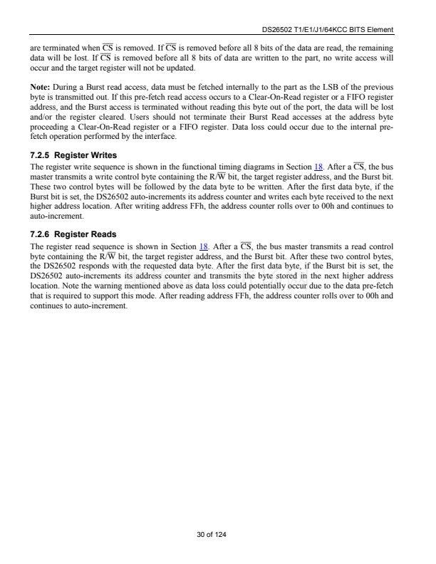
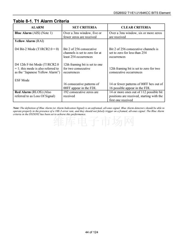
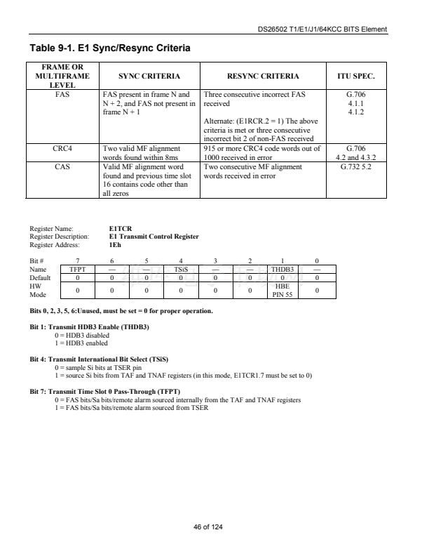
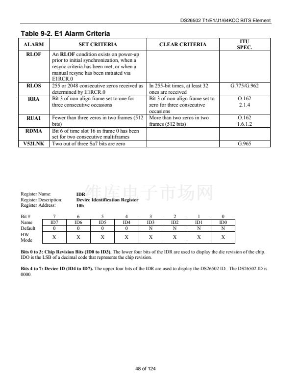
Table 9-2. E1 Alarm Criteria
ALARM
RLOF
SET CRITERIA
An
RLOF
condition exists on power-up
prior to initial synchronization, when a
resync criteria has been met, or when a
manual resync has been initiated via
E1RCR.0
255 or 2048 consecutive zeros received as
determined by E1RCR.0
Bit 3 of non-align frame set to one for
three consecutive occasions
Fewer than three zeros in two frames (512
bits)
Bit 6 of time slot 16 in frame 0 has been
set for two consecutive multiframes
Two out of three Sa7 bits are zero
CLEAR CRITERIA
ITU
SPEC.
RLOS
RRA
RUA1
RDMA
V52LNK
In 255-bit times, at least 32
ones are received
Bit 3 of non-align frame set to
zero for three consecutive
occasions
More than two zeros in two
frames (512 bits)
G.775/G.962
O.162
2.1.4
O.162
1.6.1.2
G.965
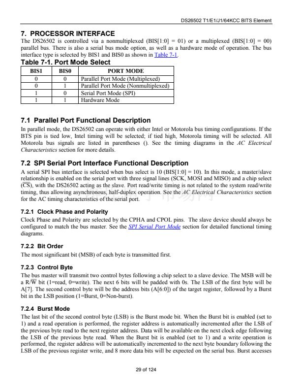
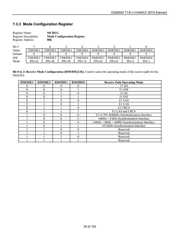
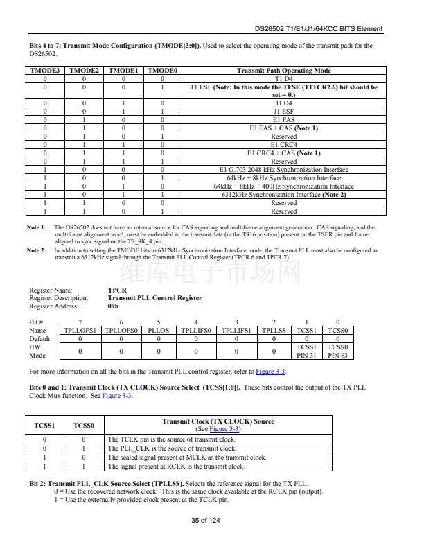
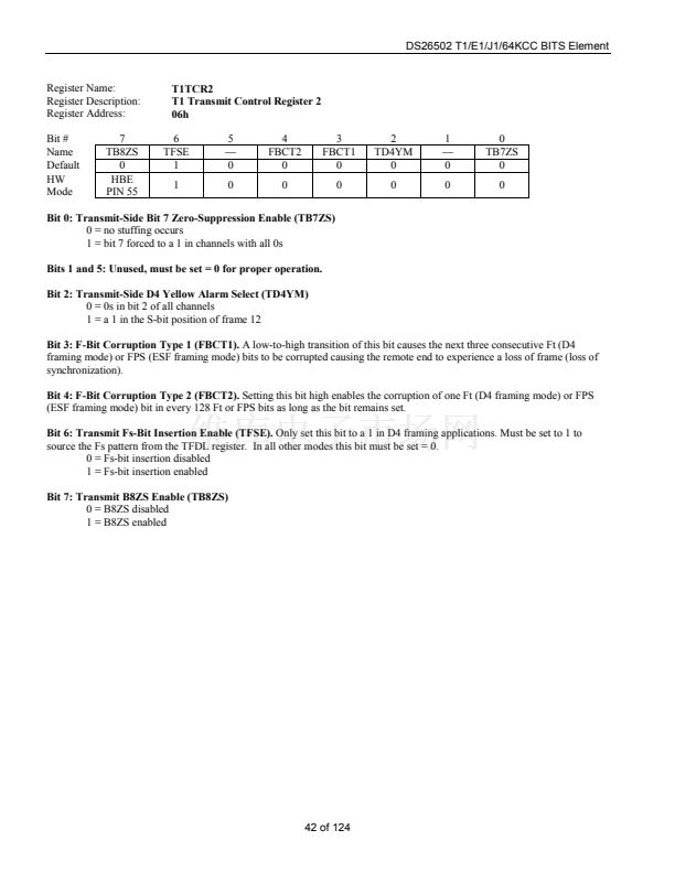
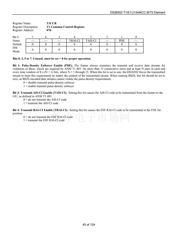
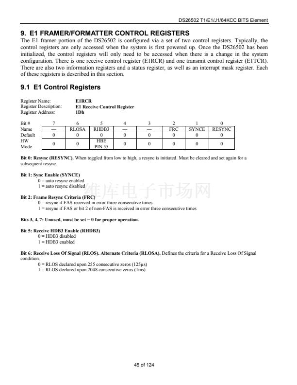
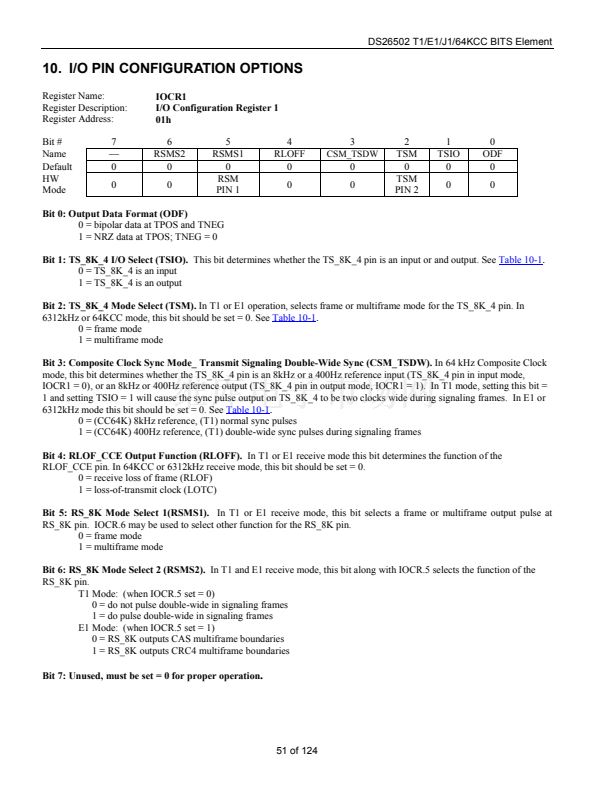
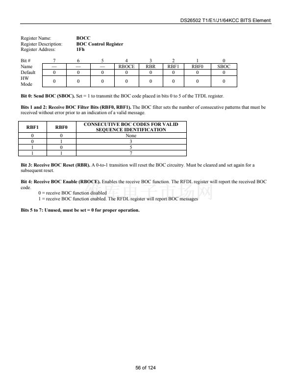
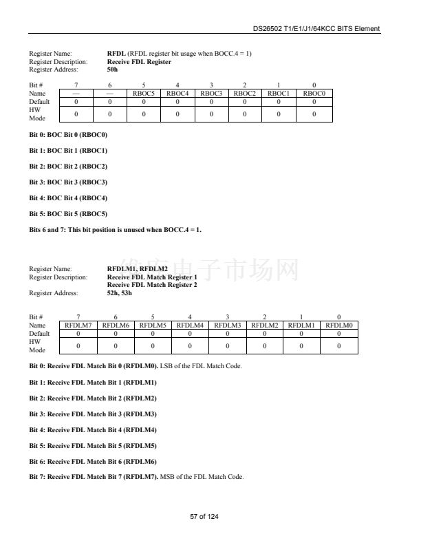
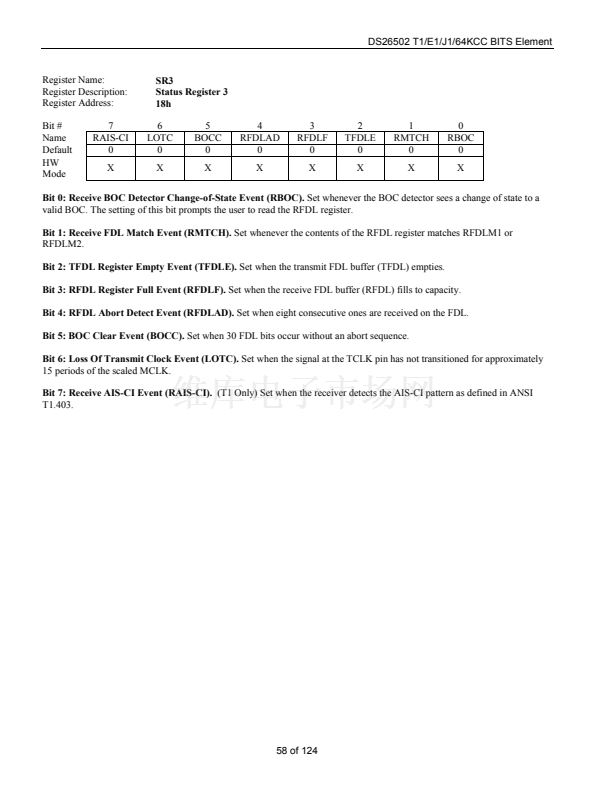
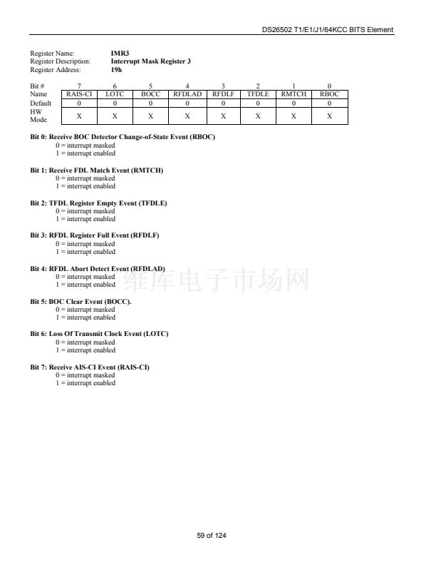
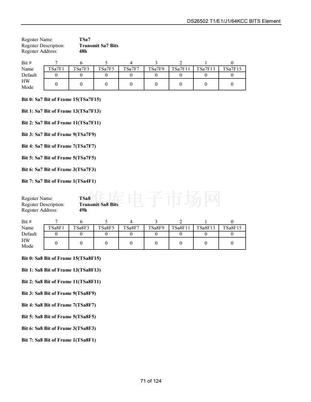
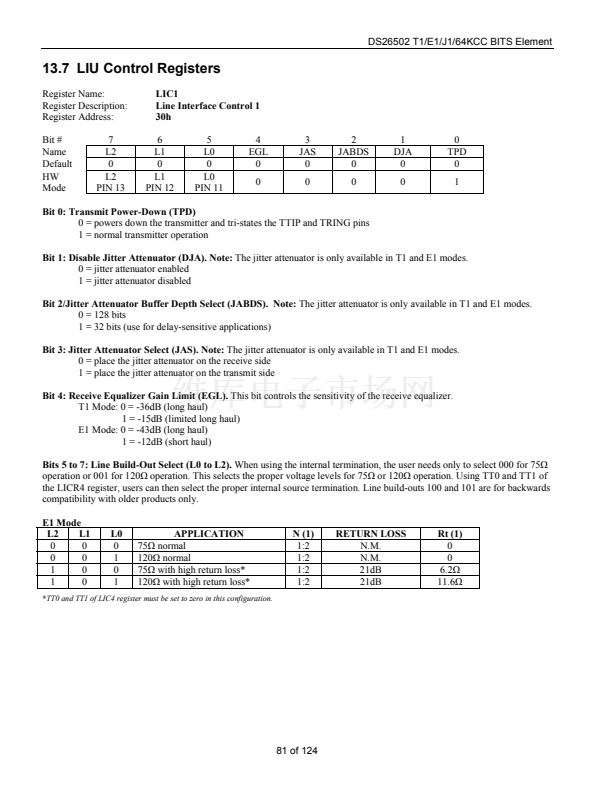
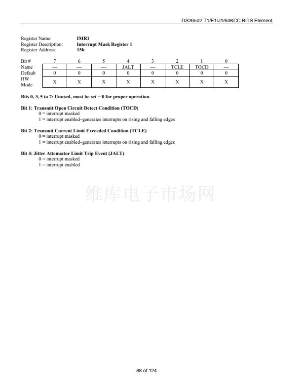
Register Name:
Register Description:
Register Address:
Bit #
Name
Default
HW
Mode
7
ID7
0
X
IDR
Device Identification Register
10h
6
ID6
0
X
5
ID5
0
X
4
ID4
0
X
3
ID3
N
X
2
ID2
N
X
1
ID1
N
X
0
ID0
N
X
Bits 0 to 3: Chip Revision Bits (ID0 to ID3).
The lower four bits of the IDR are used to display the die revision of the chip.
IDO is the LSB of a decimal code that represents the chip revision.
Bits 4 to 7: Device ID (ID4 to ID7).
The upper four bits of the IDR are used to display the DS26502 ID. The DS26502 ID is
0000.
48 of 124


 1
1
 2
2
 3
3
 4
4
 5
5
 6
6
 7
7
 8
8
 9
9
 10
10
 11
11
 12
12
 13
13
 14
14
 15
15
 16
16
 17
17
 18
18
 19
19
 20
20
 21
21
 22
22
 23
23
 24
24
 25
25
 26
26
 27
27
 28
28
 29
29
 30
30
 31
31
 32
32
 33
33
 34
34
 35
35
 36
36
 37
37
 38
38
 39
39
 40
40
 41
41
 42
42
 43
43
 44
44
 45
45
 46
46
 47
47
 48
48
 49
49
 50
50
 51
51
 52
52
 53
53
 54
54
 55
55
 56
56
 57
57
 58
58
 59
59
 60
60
 61
61
 62
62
 63
63
 64
64
 65
65
 66
66
 67
67
 68
68
 69
69
 70
70
 71
71
 72
72
 73
73
 74
74
 75
75
 76
76
 77
77
 78
78
 79
79
 80
80
 81
81
 82
82
 83
83
 84
84
 85
85
 86
86
 87
87
 88
88
 89
89
 90
90
 91
91
 92
92
 93
93
 94
94
 95
95
 96
96
 97
97
 98
98
 99
99
 100
100
 101
101
 102
102
 103
103
 104
104
 105
105
 106
106
 107
107
 108
108
 109
109
 110
110
 111
111
 112
112
 113
113
 114
114
 115
115
 116
116
 117
117
 118
118
 119
119
 120
120
 121
121
 122
122
 123
123
 124
124
