DS26502 T1/E1/J1/64KCC BITS Element
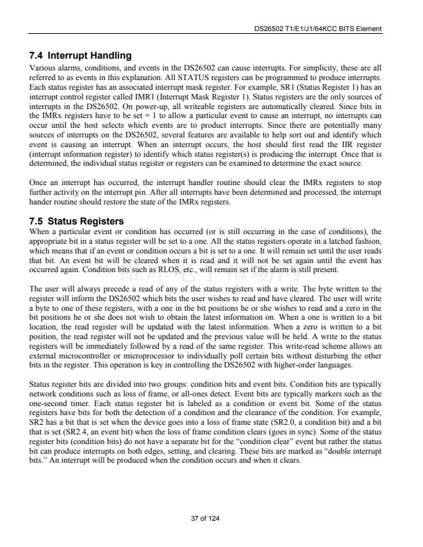
12.2 Alternate Sa/Si Bit Access Based on Double-Frame
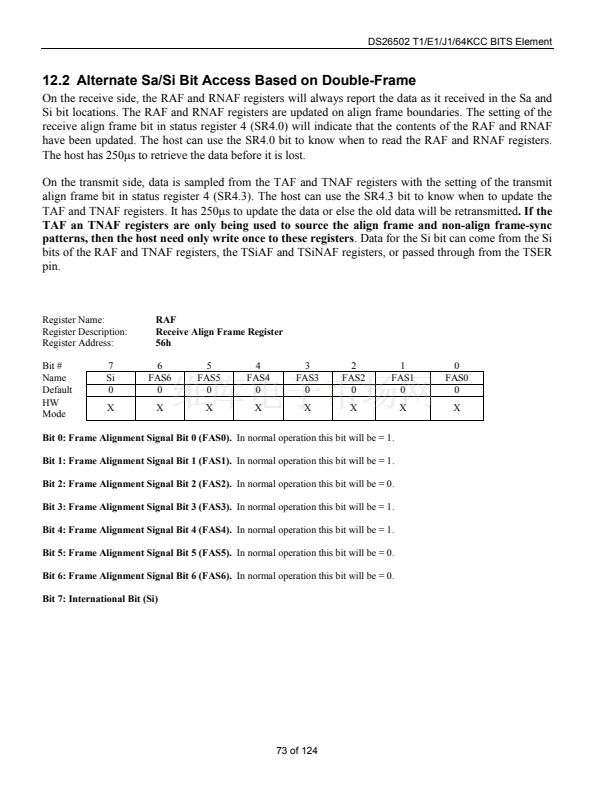
On the receive side, the RAF and RNAF registers will always report the data as it received in the Sa and
Si bit locations. The RAF and RNAF registers are updated on align frame boundaries. The setting of the
receive align frame bit in status register 4 (SR4.0) will indicate that the contents of the RAF and RNAF
have been updated. The host can use the SR4.0 bit to know when to read the RAF and RNAF registers.
The host has 250ms to retrieve the data before it is lost.
On the transmit side, data is sampled from the TAF and TNAF registers with the setting of the transmit
align frame bit in status register 4 (SR4.3). The host can use the SR4.3 bit to know when to update the
TAF and TNAF registers. It has 250ms to update the data or else the old data will be retransmitted.
If the
TAF an TNAF registers are only being used to source the align frame and non-align frame-sync
patterns, then the host need only write once to these registers.
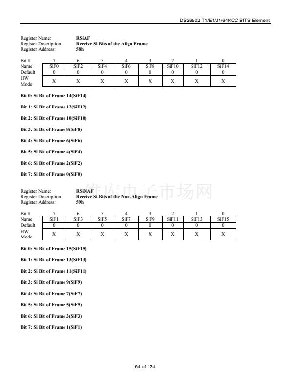
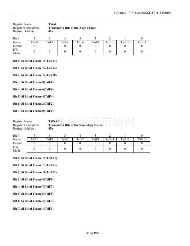
Data for the Si bit can come from the Si
bits of the RAF and TNAF registers, the TSiAF and TSiNAF registers, or passed through from the TSER
pin.
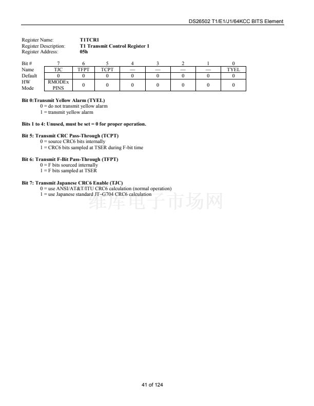
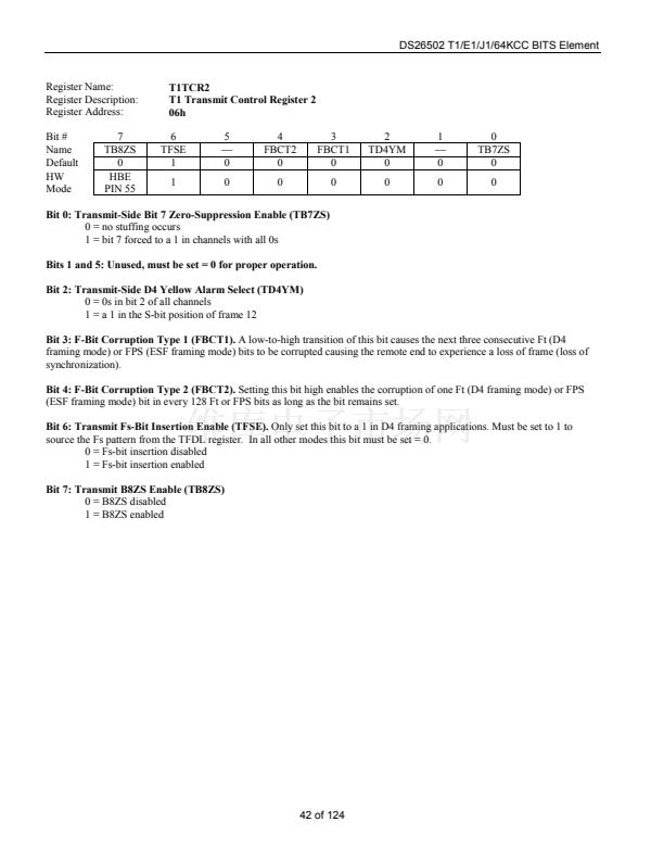
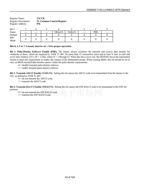
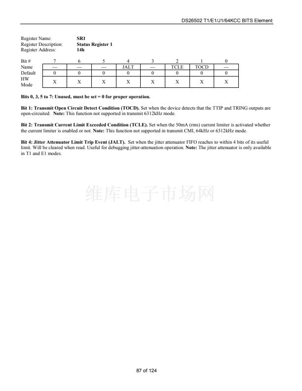
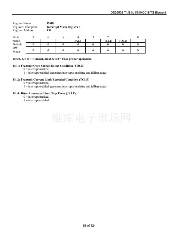
Register Name:
Register Description:
Register Address:
Bit #
Name
Default
HW
Mode
7
Si
0
X
RAF
Receive Align Frame Register
56h
6
FAS6
0
X
5
FAS5
0
X
4
FAS4
0
X
3
FAS3
0
X
2
FAS2
0
X
1
FAS1
0
X
0
FAS0
0
X
Bit 0: Frame Alignment Signal Bit 0 (FAS0).
In normal operation this bit will be = 1.
Bit 1: Frame Alignment Signal Bit 1 (FAS1).
In normal operation this bit will be = 1.
Bit 2: Frame Alignment Signal Bit 2 (FAS2).
In normal operation this bit will be = 0.
Bit 3: Frame Alignment Signal Bit 3 (FAS3).
In normal operation this bit will be = 1.
Bit 4: Frame Alignment Signal Bit 4 (FAS4).
In normal operation this bit will be = 1.
Bit 5: Frame Alignment Signal Bit 5 (FAS5).
In normal operation this bit will be = 0.
Bit 6: Frame Alignment Signal Bit 6 (FAS6).
In normal operation this bit will be = 0.
Bit 7: International Bit (Si)
73 of 124


 1
1
 2
2
 3
3
 4
4
 5
5
 6
6
 7
7
 8
8
 9
9
 10
10
 11
11
 12
12
 13
13
 14
14
 15
15
 16
16
 17
17
 18
18
 19
19
 20
20
 21
21
 22
22
 23
23
 24
24
 25
25
 26
26
 27
27
 28
28
 29
29
 30
30
 31
31
 32
32
 33
33
 34
34
 35
35
 36
36
 37
37
 38
38
 39
39
 40
40
 41
41
 42
42
 43
43
 44
44
 45
45
 46
46
 47
47
 48
48
 49
49
 50
50
 51
51
 52
52
 53
53
 54
54
 55
55
 56
56
 57
57
 58
58
 59
59
 60
60
 61
61
 62
62
 63
63
 64
64
 65
65
 66
66
 67
67
 68
68
 69
69
 70
70
 71
71
 72
72
 73
73
 74
74
 75
75
 76
76
 77
77
 78
78
 79
79
 80
80
 81
81
 82
82
 83
83
 84
84
 85
85
 86
86
 87
87
 88
88
 89
89
 90
90
 91
91
 92
92
 93
93
 94
94
 95
95
 96
96
 97
97
 98
98
 99
99
 100
100
 101
101
 102
102
 103
103
 104
104
 105
105
 106
106
 107
107
 108
108
 109
109
 110
110
 111
111
 112
112
 113
113
 114
114
 115
115
 116
116
 117
117
 118
118
 119
119
 120
120
 121
121
 122
122
 123
123
 124
124
