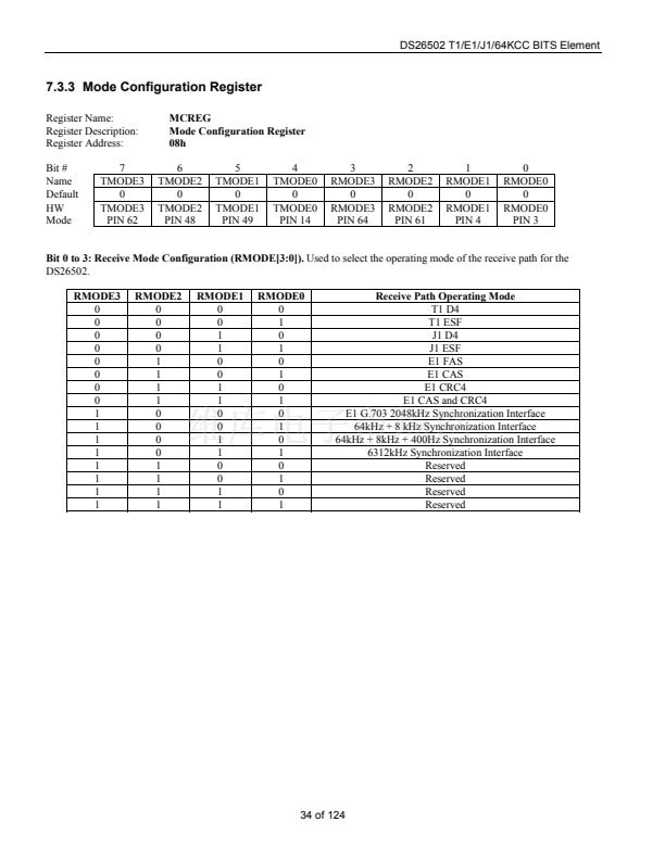
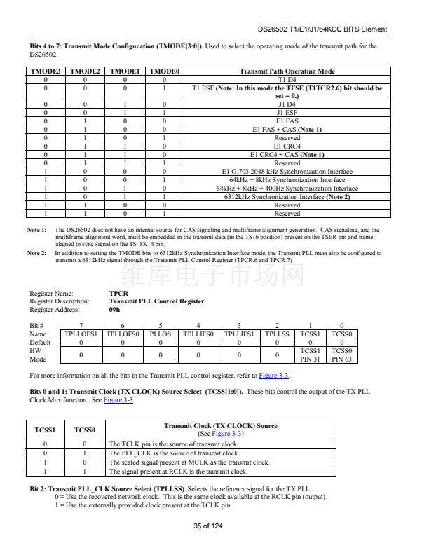
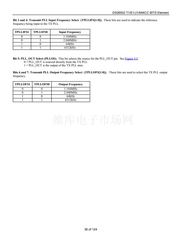
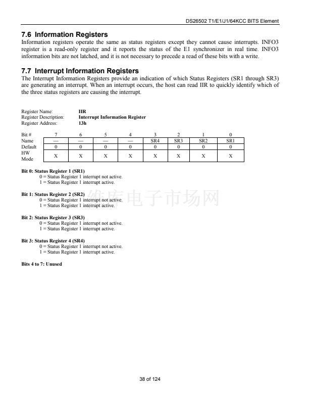
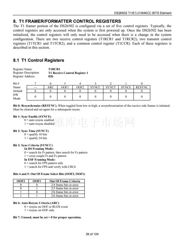
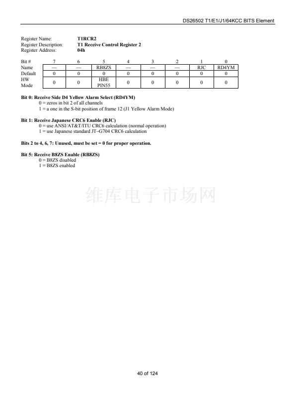
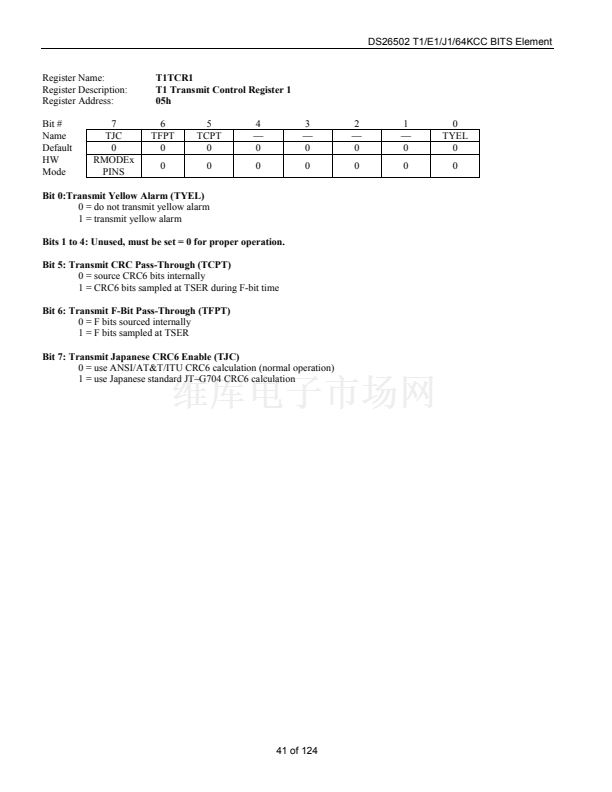
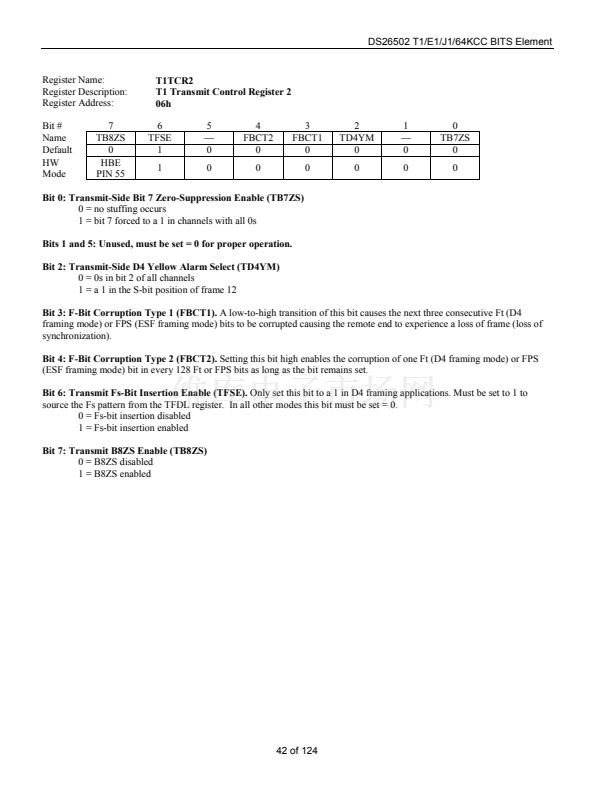
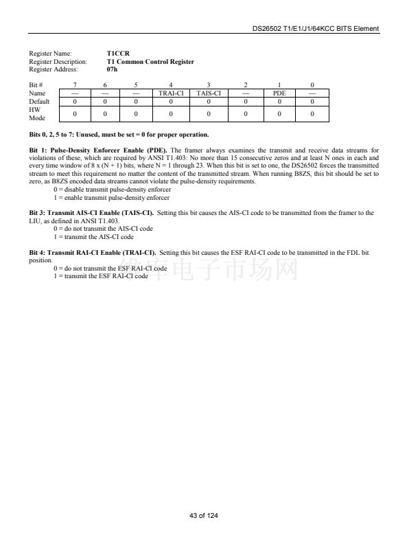
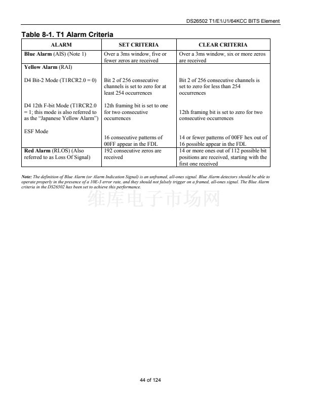
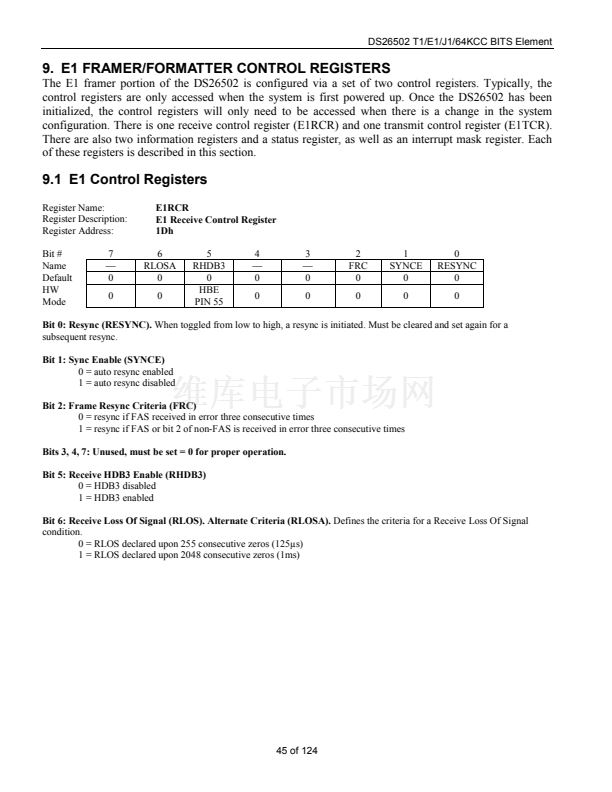
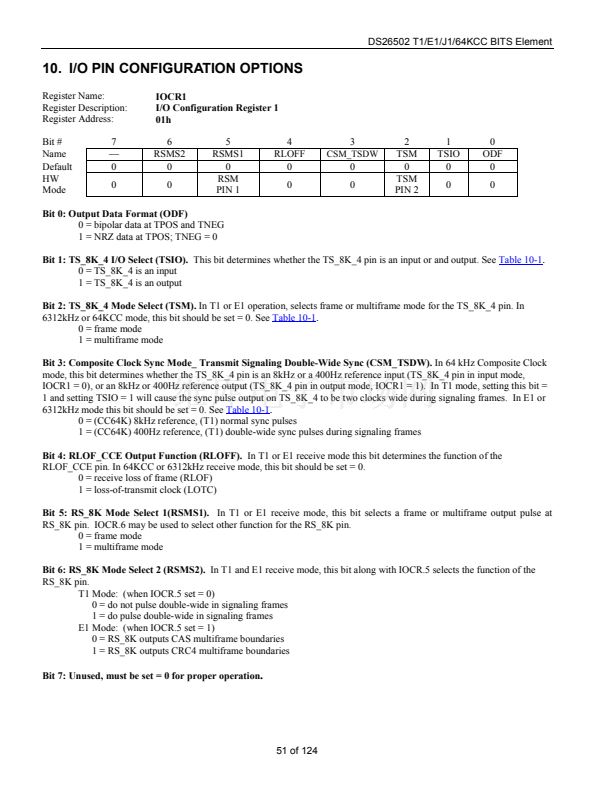
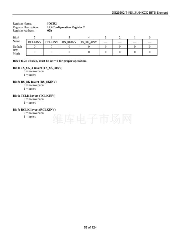
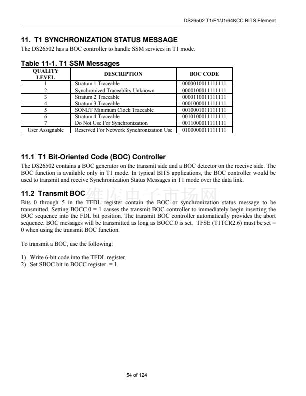
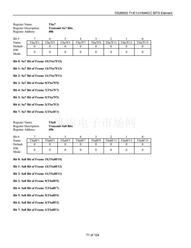
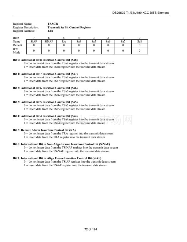
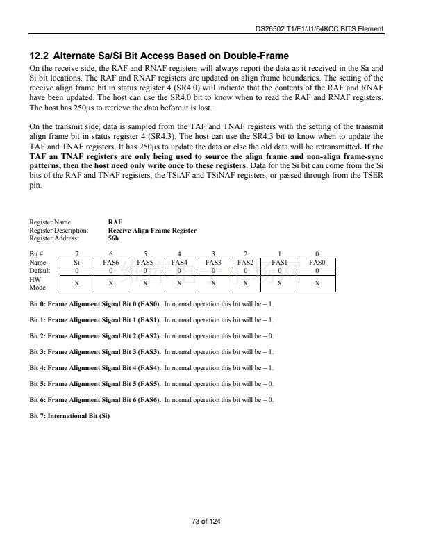
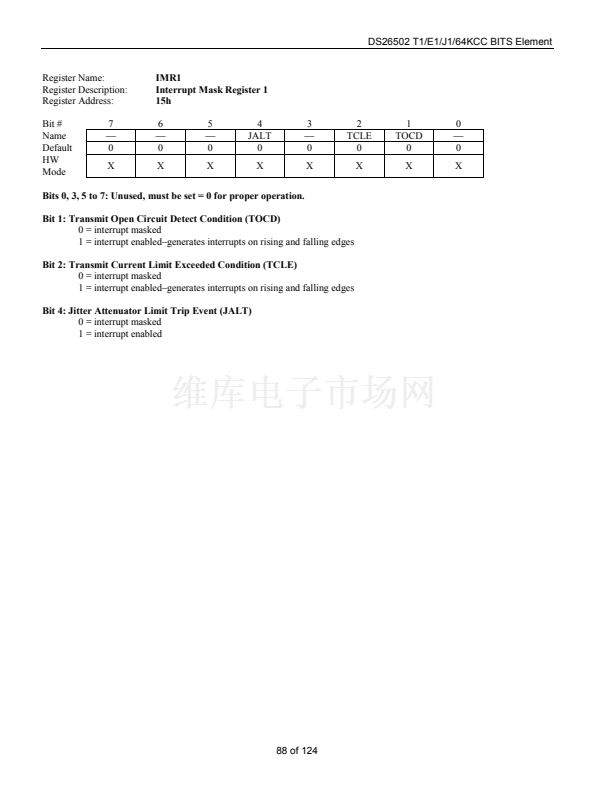
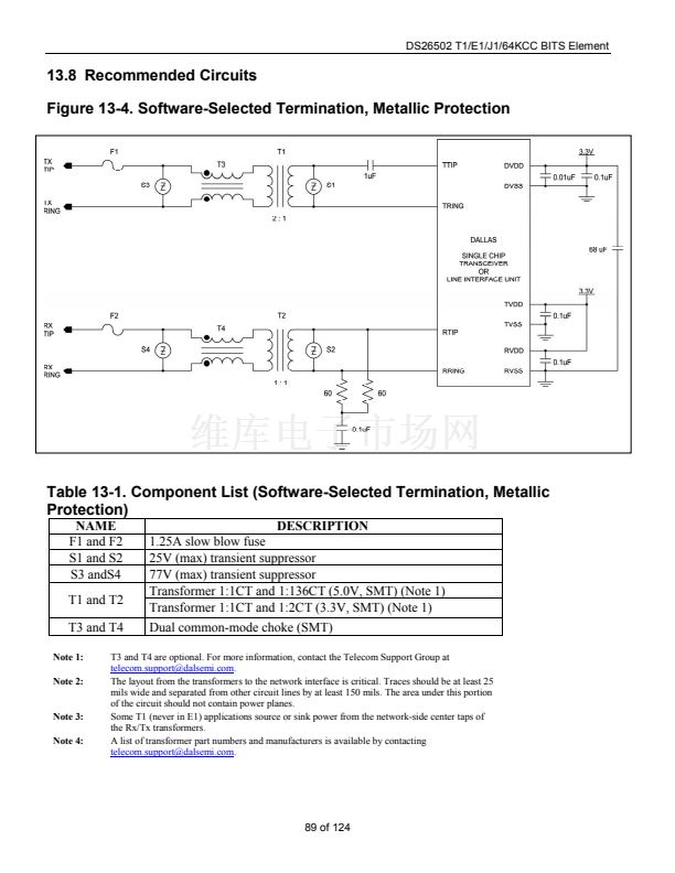
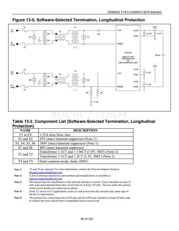
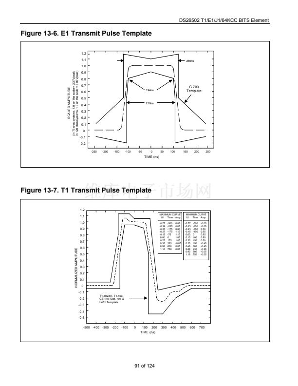
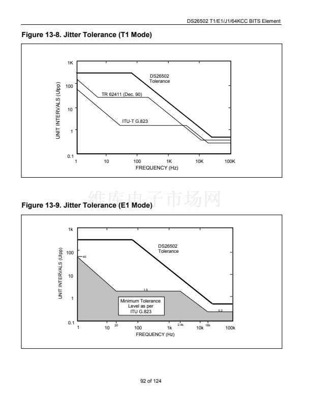
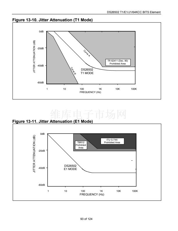
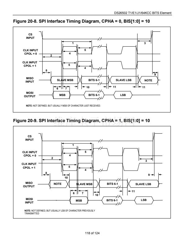
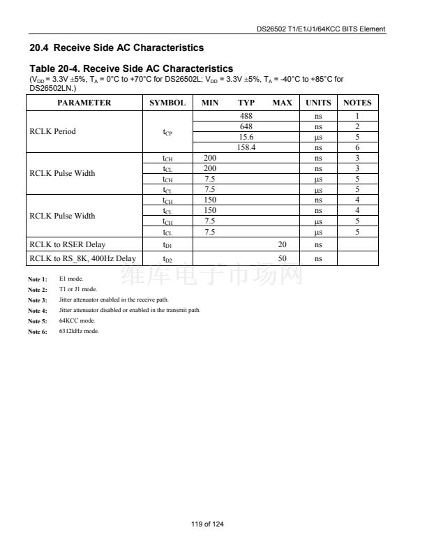
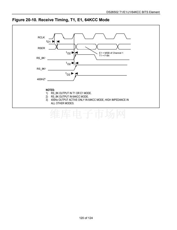
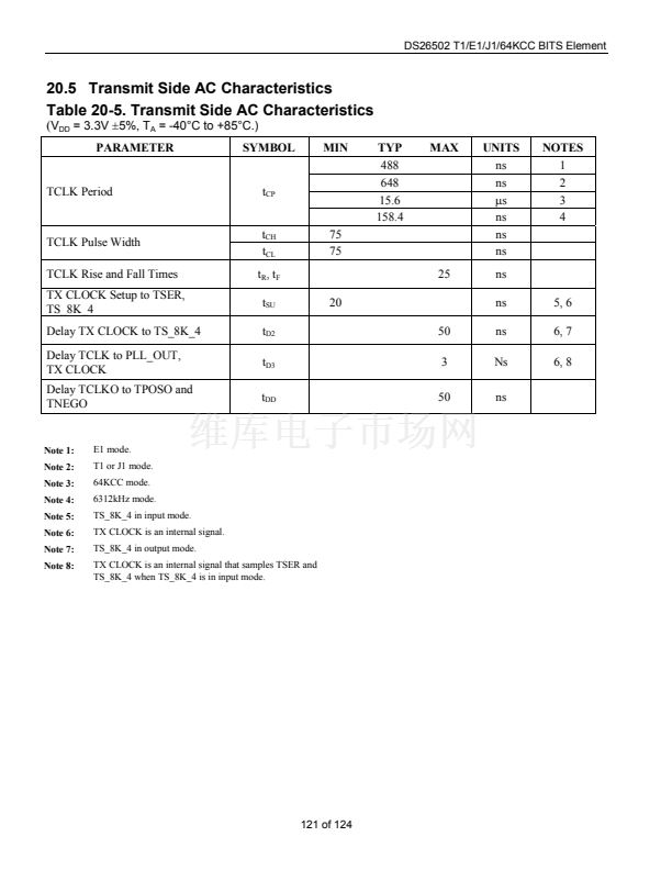
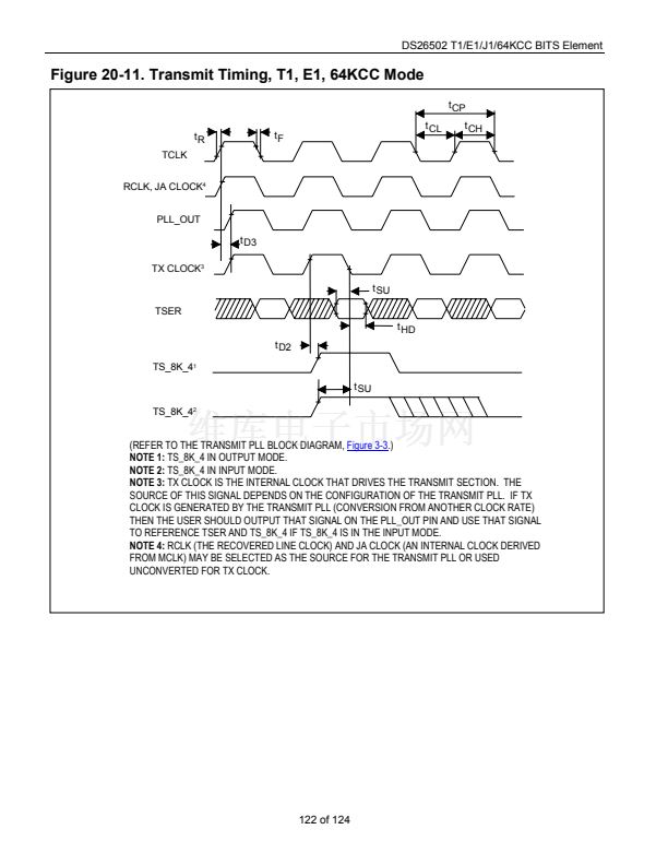
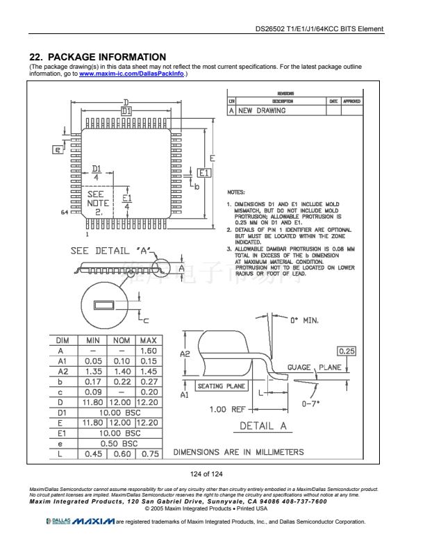
DS26502 T1/E1/J1/64KCC BITS Element
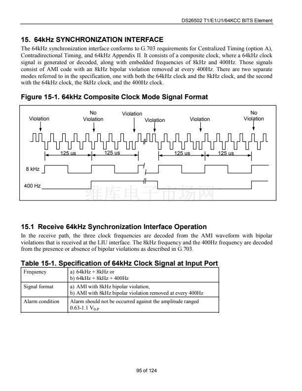
16. 6312kHz SYNCHRONIZATION INTERFACE
The DS26502 has a 6312kHz Synchronization Interface mode of operation that conforms with Appendix
II.2 of G.703, with the exception that the DS26502 transmits a square wave as opposed to the sine wave
that is defined in the G.703 specification.
16.1 Receive 6312kHz Synchronization Interface Operation
On the receive interface, a 6312kHz sine wave is accepted conforming to the input port requirements of
G.703 Appendix II. Alternatively, a 6312kHz square wave will also be accepted. A 6312kHz square wave
is output on RCLK in the receive direction. RS_8K and 400Hz are not driven in this mode and will be tri-
stated.
Table 16-1. Specification of 6312kHz Clock
Signal at Input Port
Frequency
Signal format
Alarm condition
6312kHz
Sinusoidal wave
Alarm should not be occurred against
the amplitude ranged
-16dBm to +3dBm
16.2 Transmit 6312kHz Synchronization Interface Operation
On the transmit interface, a nominally 50% duty cycle, 6312kHz square wave at standard logic levels is
available from the PLL_OUT pin. In normal operation, the TCLKO pin will output the same signal.
However, if remote loopback is enabled then TCLKO will be replaced with the recovered receive clock.
See
Figure 3-1.
The G.703 requirements for the 6312kHz transmitted signal are shown in
Table 16-2.
The
user must provide an external circuit to convert the TCLKO or PLL_OUT signal to the level and
impedance required by G.703. The RSER and TS_8K-4 pins are ignored in this mode. TTIP and TRING
will be tri-stated in this mode.
Table 16-2. Specification of 6312kHz Clock
Signal at Output Port
Frequency
Load impedance
Transmission media
Amplitude
6312kHz
75W resistive
Coaxial pair cable
0dBm
卤
3dBm
97 of 124


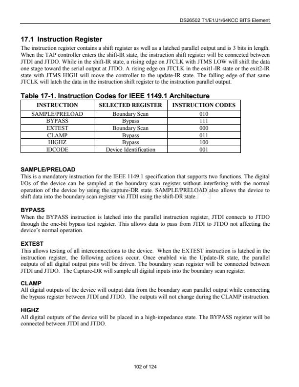
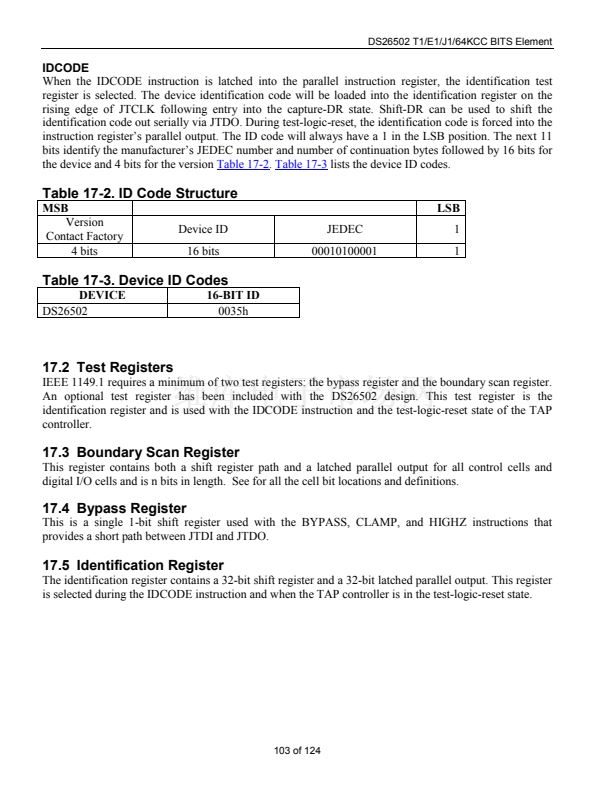
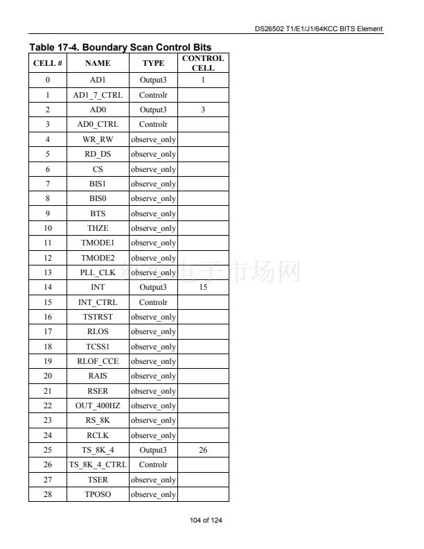
 1
1
 2
2
 3
3
 4
4
 5
5
 6
6
 7
7
 8
8
 9
9
 10
10
 11
11
 12
12
 13
13
 14
14
 15
15
 16
16
 17
17
 18
18
 19
19
 20
20
 21
21
 22
22
 23
23
 24
24
 25
25
 26
26
 27
27
 28
28
 29
29
 30
30
 31
31
 32
32
 33
33
 34
34
 35
35
 36
36
 37
37
 38
38
 39
39
 40
40
 41
41
 42
42
 43
43
 44
44
 45
45
 46
46
 47
47
 48
48
 49
49
 50
50
 51
51
 52
52
 53
53
 54
54
 55
55
 56
56
 57
57
 58
58
 59
59
 60
60
 61
61
 62
62
 63
63
 64
64
 65
65
 66
66
 67
67
 68
68
 69
69
 70
70
 71
71
 72
72
 73
73
 74
74
 75
75
 76
76
 77
77
 78
78
 79
79
 80
80
 81
81
 82
82
 83
83
 84
84
 85
85
 86
86
 87
87
 88
88
 89
89
 90
90
 91
91
 92
92
 93
93
 94
94
 95
95
 96
96
 97
97
 98
98
 99
99
 100
100
 101
101
 102
102
 103
103
 104
104
 105
105
 106
106
 107
107
 108
108
 109
109
 110
110
 111
111
 112
112
 113
113
 114
114
 115
115
 116
116
 117
117
 118
118
 119
119
 120
120
 121
121
 122
122
 123
123
 124
124
