鈥?On the F2810 and F2812 devices, the VMAP and M0M1MAP modes are set to 鈥?鈥?on reset. The ENPIE mode is forced to 鈥?鈥?on reset.
鈥?Vector map M1 Vector is a reserved mode only.
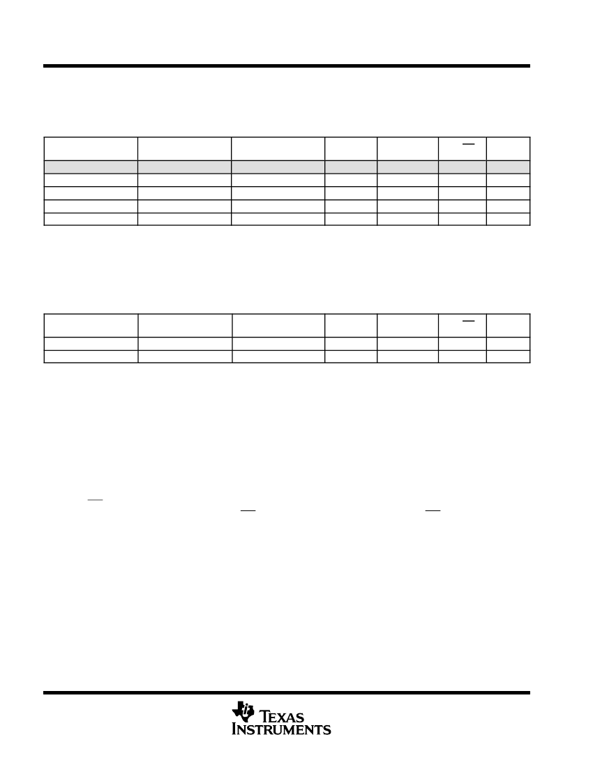
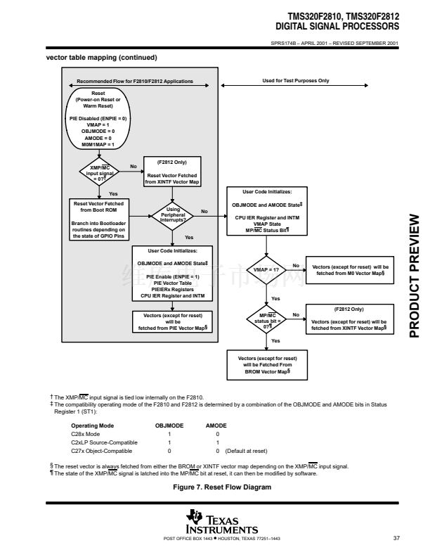
After reset operation, the vector table will be located in the areas listed in Table 20.
Table 20. Vector Table Mapping After Reset Operation
鈥?/div>
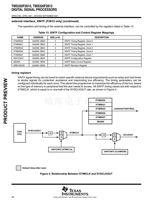
VECTOR MAPS
BROM Vector
XINTF Vector搂
RESET FETCHED
FROM
ROM Block
XINTF Zone 7 Block
ADDRESS RANGE
0x3FFFC0鈥?x3FFFFF
0x3FFFC0鈥?x3FFFFF
VMAP
1
1
M0M1MAP
1
1
MP/MC
0
1
ENPIE
0
0
鈥?On the F2810 and F2812 devices, the VMAP and M0M1MAP modes are set to 鈥?鈥?on reset. The ENPIE mode is forced to 鈥?鈥?on reset.
搂 Valid on F2812 only
The vector mapping is controlled by the following mode bits/signals:
VMAP:
This bit is found in Status Register 1 (bit 3). A device reset sets this bit to 1. The state of this
bit can be modified by writing to ST1 or by 鈥淪ETC/CLRC VMAP鈥?instructions.
This bit is found in Status Register 1 (bit 11). A device reset sets this bit to 1. The state of this
bit can be modified by writing to ST1 or by 鈥淪ETC/CLRC M0M1MAP鈥?instructions. This bit
should remain set. M0M1MAP = 0 is reserved for TI testing.
This bit is found in XINTCNF2 Register (bit 8). On the F2812, the default value of this bit, on
reset, is set by the XMP/MC input device signal. On the F2810, XMP/MC is tied low internally.
The state of this bit can be modified by writing to the XINTCNF2 register (address 0x0000
0B34).
This bit is found in PIECTRL Register (bit 0). The default value of this bit, on reset, is set to 鈥?鈥?/div>
(PIE disabled). The state of this bit can be modified by writing to the PIECTRL register
(address 0x0000 0CE0).
M0M1MAP:
MP/MC:
ENPIE:
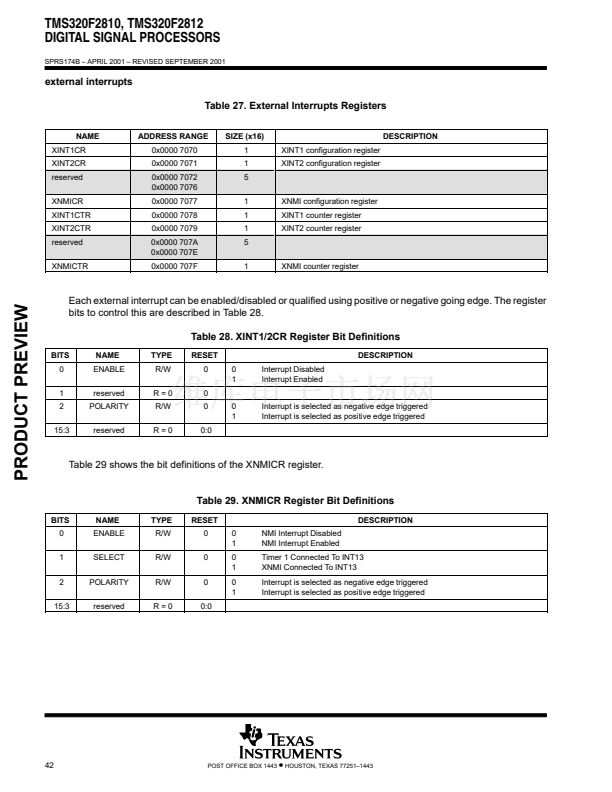
The external interrupts are configured using the registers listed in Table 27.
36
POST OFFICE BOX 1443
鈥?/div>
HOUSTON, TEXAS 77251鈥?443


 1
1
 2
2
 3
3
 4
4
 5
5
 6
6
 7
7
 8
8
 9
9
 10
10
 11
11
 12
12
 13
13
 14
14
 15
15
 16
16
 17
17
 18
18
 19
19
 20
20
 21
21
 22
22
 23
23
 24
24
 25
25
 26
26
 27
27
 28
28
 29
29
 30
30
 31
31
 32
32
 33
33
 34
34
 35
35
 36
36
 37
37
 38
38
 39
39
 40
40
 41
41
 42
42
 43
43
 44
44
 45
45
 46
46
 47
47
 48
48
 49
49
 50
50
 51
51
 52
52
 53
53
 54
54
 55
55
 56
56
 57
57
 58
58
 59
59
 60
60
 61
61
 62
62
 63
63
 64
64
 65
65
 66
66
 67
67
 68
68
 69
69
 70
70
 71
71
 72
72
 73
73
 74
74
 75
75
 76
76
 77
77
 78
78
 79
79
 80
80
 81
81
 82
82
 83
83
 84
84
 85
85
 86
86
 87
87
 88
88
 89
89
 90
90
 91
91
 92
92
 93
93
 94
94
 95
95
 96
96
 97
97
 98
98
 99
99
 100
100
 101
101
 102
102
 103
103
