TMS320F2810, TMS320F2812
DIGITAL SIGNAL PROCESSORS
SPRS174B 鈥?APRIL 2001 鈥?REVISED SEPTEMBER 2001
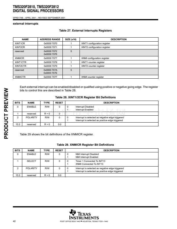
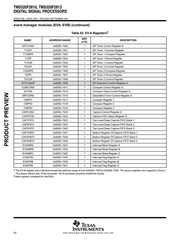
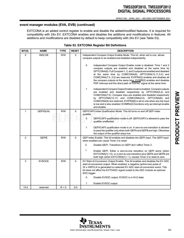
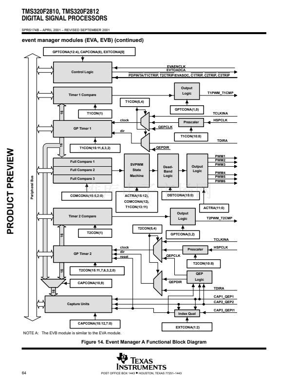
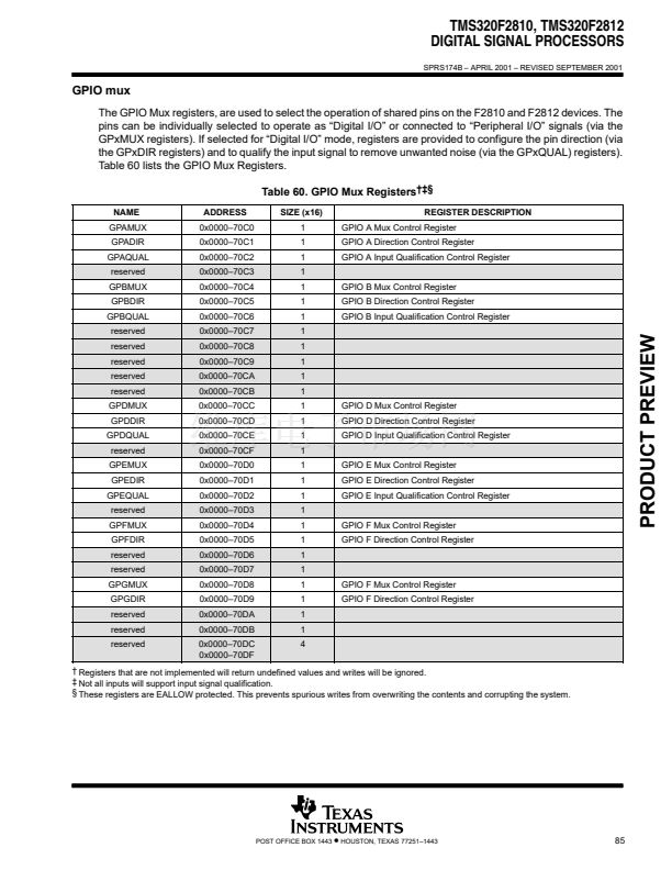
enhanced analog-to-digital converter (ADC) module (continued)
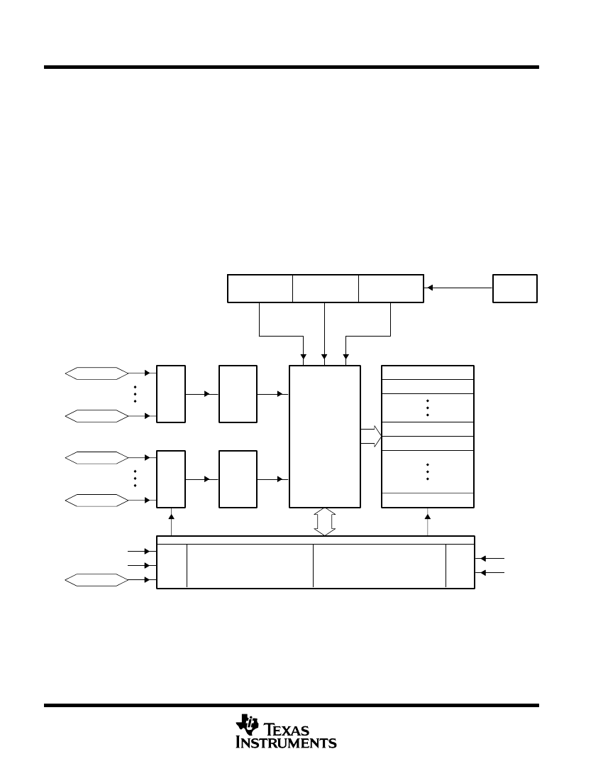
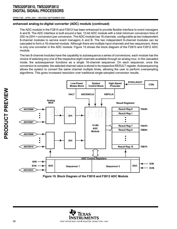
The ADC module in the F2810 and F2812 has been enhanced to provide flexible interface to event managers
A and B. The ADC interface is built around a fast, 12-bit ADC module with a total minimum conversion time of
200 ns (S/H + conversion) per conversion. The ADC module has 16 channels, configurable as two independent
8-channel modules to service event managers A and B. The two independent 8-channel modules can be
cascaded to form a 16-channel module. Although there are multiple input channels and two sequencers, there
is only one converter in the ADC module. Figure 15 shows the block diagram of the F2810 and F2812 ADC
module.
The two 8-channel modules have the capability to autosequence a series of conversions, each module has the
choice of selecting any one of the respective eight channels available through an analog mux. In the cascaded
mode, the autosequencer functions as a single 16-channel sequencer. On each sequencer, once the
conversion is complete, the selected channel value is stored in its respective RESULT register. Autosequencing
allows the system to convert the same channel multiple times, allowing the user to perform oversampling
algorithms. This gives increased resolution over traditional single-sampled conversion results.
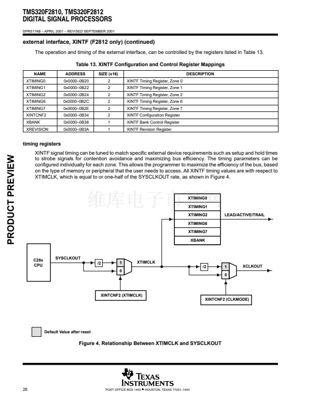
SYSCLKOUT
C28x
Low-Power
Modes Block
System
Control Block
High-Speed
Prescaler
PRODUCT PREVIEW
HALT
Analog
MUX
ADCIN00
S/H
ADCIN07
ADCENCLK
HSPCLK
Result Registers
Result Reg 0
Result Reg 1
70A8h
12-Bit
ADC
Module
ADCIN08
S/H
ADCIN15
Result Reg 7
Result Reg 8
70AFh
70B0h
Result Reg 15
70B7h
ADC Control Registers
S/W
EVA
ADCSOC
SOC
Sequencer 1
Sequencer 2
SOC
S/W
EVB
Figure 15. Block Diagram of the F2810 and F2812 ADC Module
68
POST OFFICE BOX 1443
鈥?/div>
HOUSTON, TEXAS 77251鈥?443


 1
1
 2
2
 3
3
 4
4
 5
5
 6
6
 7
7
 8
8
 9
9
 10
10
 11
11
 12
12
 13
13
 14
14
 15
15
 16
16
 17
17
 18
18
 19
19
 20
20
 21
21
 22
22
 23
23
 24
24
 25
25
 26
26
 27
27
 28
28
 29
29
 30
30
 31
31
 32
32
 33
33
 34
34
 35
35
 36
36
 37
37
 38
38
 39
39
 40
40
 41
41
 42
42
 43
43
 44
44
 45
45
 46
46
 47
47
 48
48
 49
49
 50
50
 51
51
 52
52
 53
53
 54
54
 55
55
 56
56
 57
57
 58
58
 59
59
 60
60
 61
61
 62
62
 63
63
 64
64
 65
65
 66
66
 67
67
 68
68
 69
69
 70
70
 71
71
 72
72
 73
73
 74
74
 75
75
 76
76
 77
77
 78
78
 79
79
 80
80
 81
81
 82
82
 83
83
 84
84
 85
85
 86
86
 87
87
 88
88
 89
89
 90
90
 91
91
 92
92
 93
93
 94
94
 95
95
 96
96
 97
97
 98
98
 99
99
 100
100
 101
101
 102
102
 103
103
