TMS320F2810, TMS320F2812
DIGITAL SIGNAL PROCESSORS
SPRS174B 鈥?APRIL 2001 鈥?REVISED SEPTEMBER 2001
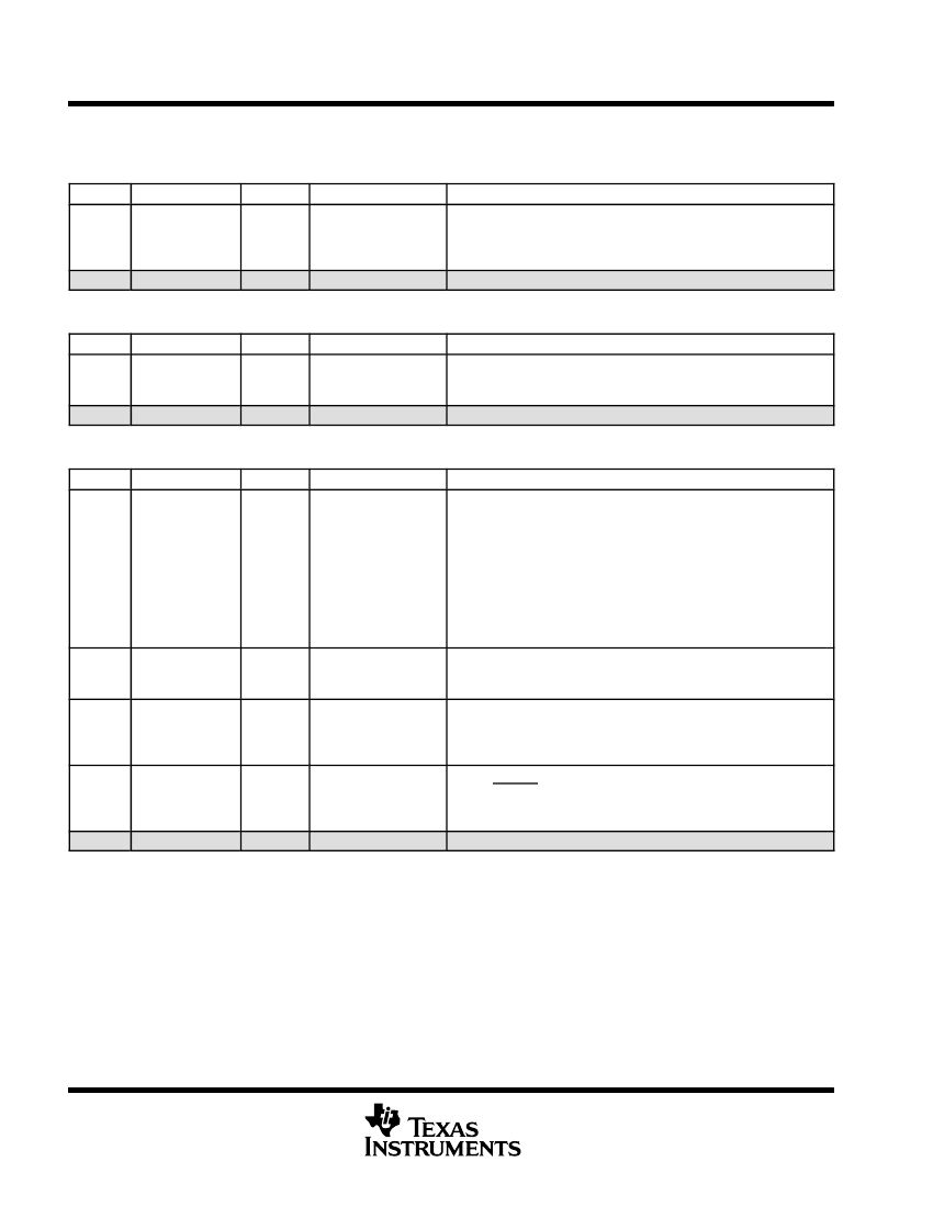
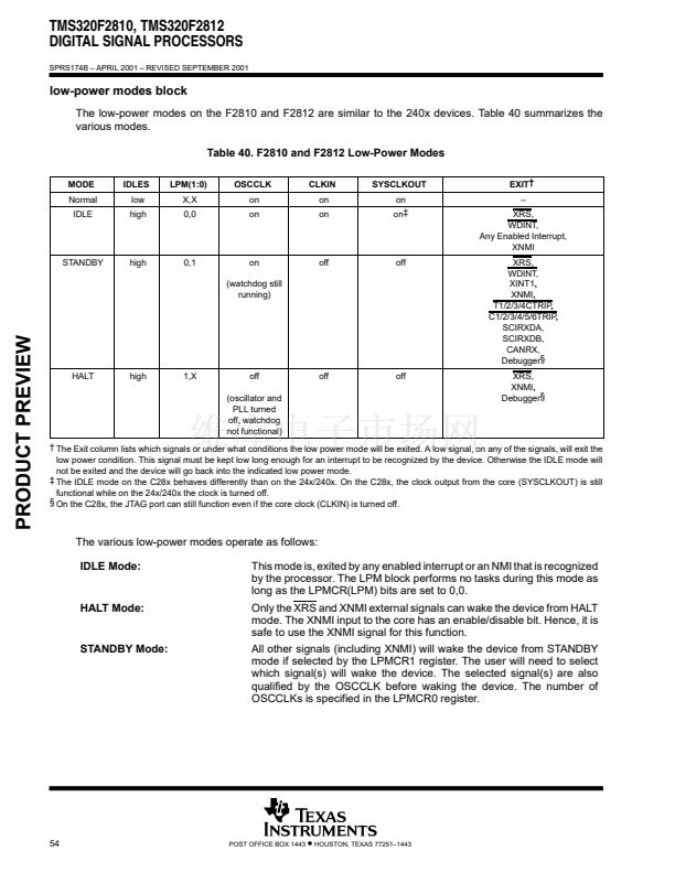
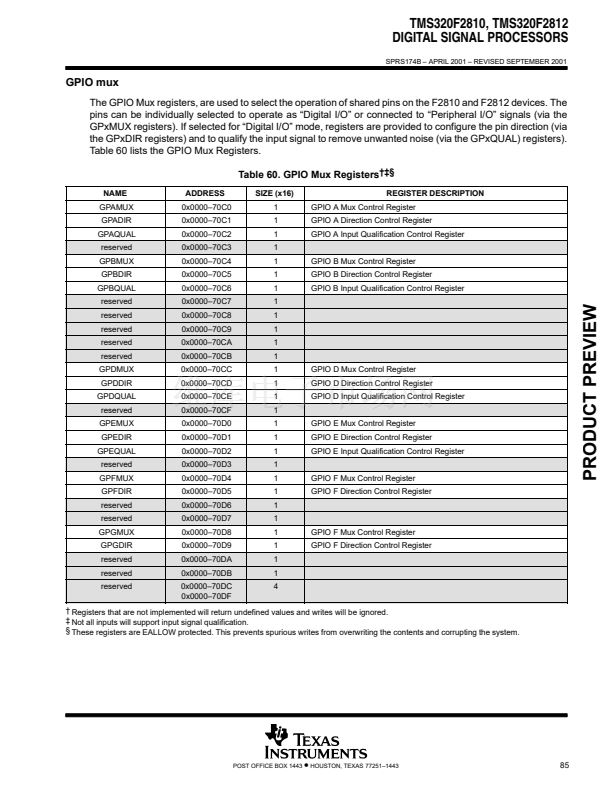
watchdog block (continued)
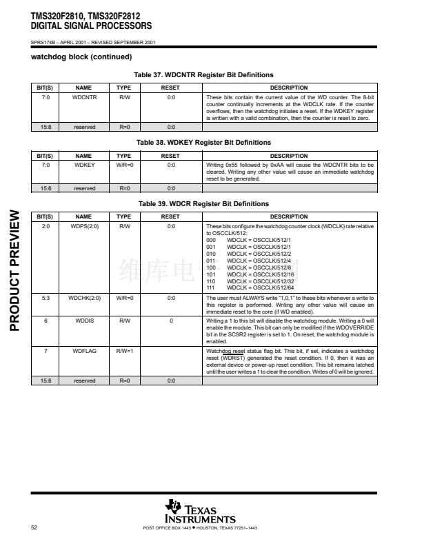
Table 37. WDCNTR Register Bit Definitions
BIT(S)
7:0
NAME
WDCNTR
TYPE
R/W
RESET
0:0
DESCRIPTION
These bits contain the current value of the WD counter. The 8-bit
counter continually increments at the WDCLK rate. If the counter
overflows, then the watchdog initiates a reset. If the WDKEY register
is written with a valid combination, then the counter is reset to zero.
15:8
reserved
R=0
0:0
Table 38. WDKEY Register Bit Definitions
BIT(S)
7:0
NAME
WDKEY
TYPE
W/R=0
RESET
0:0
DESCRIPTION
Writing 0x55 followed by 0xAA will cause the WDCNTR bits to be
cleared. Writing any other value will cause an immediate watchdog
reset to be generated.
15:8
reserved
R=0
0:0
Table 39. WDCR Register Bit Definitions
PRODUCT PREVIEW
BIT(S)
2:0
NAME
WDPS(2:0)
TYPE
R/W
RESET
0:0
DESCRIPTION
These bits configure the watchdog counter clock (WDCLK) rate relative
to OSCCLK/512:
000
WDCLK = OSCCLK/512/1
001
WDCLK = OSCCLK/512/1
010
WDCLK = OSCCLK/512/2
011
WDCLK = OSCCLK/512/4
100
WDCLK = OSCCLK/512/8
101
WDCLK = OSCCLK/512/16
110
WDCLK = OSCCLK/512/32
111
WDCLK = OSCCLK/512/64
The user must ALWAYS write 鈥?,0,1鈥?to these bits whenever a write to
this register is performed. Writing any other value will cause an
immediate reset to the core (if WD enabled).
Writing a 1 to this bit will disable the watchdog module. Writing a 0 will
enable the module. This bit can only be modified if the WDOVERRIDE
bit in the SCSR2 register is set to 1. On reset, the watchdog module is
enabled.
Watchdog reset status flag bit. This bit, if set, indicates a watchdog
reset (WDRST) generated the reset condition. If 0, then it was an
external device or power-up reset condition. This bit remains latched
until the user writes a 1 to clear the condition. Writes of 0 will be ignored.
5:3
WDCHK(2:0)
W/R=0
0:0
6
WDDIS
R/W
0
7
WDFLAG
R/W=1
15:8
reserved
R=0
0:0
52
POST OFFICE BOX 1443
鈥?/div>
HOUSTON, TEXAS 77251鈥?443


 1
1
 2
2
 3
3
 4
4
 5
5
 6
6
 7
7
 8
8
 9
9
 10
10
 11
11
 12
12
 13
13
 14
14
 15
15
 16
16
 17
17
 18
18
 19
19
 20
20
 21
21
 22
22
 23
23
 24
24
 25
25
 26
26
 27
27
 28
28
 29
29
 30
30
 31
31
 32
32
 33
33
 34
34
 35
35
 36
36
 37
37
 38
38
 39
39
 40
40
 41
41
 42
42
 43
43
 44
44
 45
45
 46
46
 47
47
 48
48
 49
49
 50
50
 51
51
 52
52
 53
53
 54
54
 55
55
 56
56
 57
57
 58
58
 59
59
 60
60
 61
61
 62
62
 63
63
 64
64
 65
65
 66
66
 67
67
 68
68
 69
69
 70
70
 71
71
 72
72
 73
73
 74
74
 75
75
 76
76
 77
77
 78
78
 79
79
 80
80
 81
81
 82
82
 83
83
 84
84
 85
85
 86
86
 87
87
 88
88
 89
89
 90
90
 91
91
 92
92
 93
93
 94
94
 95
95
 96
96
 97
97
 98
98
 99
99
 100
100
 101
101
 102
102
 103
103
