RESET鈥?/div>
0,0
1:1
DESCRIPTION
These bits set the low power mode for the device.
Select number of OSCCLK clock cycles to qualify the selected inputs when
waking the LPM from STANDBY mode:
000000 = 2 OSCCLKs
000001 = 3 OSCCLKs
.
111111 = 65 OSCCLKs
15:8
reserved
R=0
0:0
鈥?These bits are cleared by a reset (XRS).
鈥?The low power mode bits (LPM) are only valid when the IDLE instruction is executed. Therefore, the user must set the LPM bits to the appropriate
mode before executing the IDLE instruction.
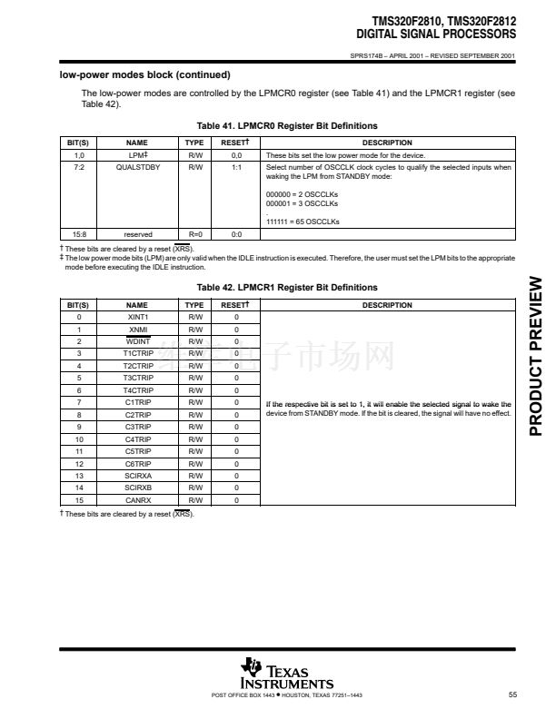
Table 42. LPMCR1 Register Bit Definitions
BIT(S)
0
1
2
3
4
5
6
7
8
9
10
11
12
13
14
15
NAME
XINT1
XNMI
WDINT
T1CTRIP
T2CTRIP
T3CTRIP
T4CTRIP
C1TRIP
C2TRIP
C3TRIP
C4TRIP
C5TRIP
C6TRIP
SCIRXA
SCIRXB
CANRX
TYPE
R/W
R/W
R/W
R/W
R/W
R/W
R/W
R/W
R/W
R/W
R/W
R/W
R/W
R/W
R/W
R/W
RESET鈥?/div>
0
0
0
0
0
0
0
0
0
0
0
0
0
0
0
0
If the res ective bit is set to 1, it will enable the selected signal to wake the
respective
device from STANDBY mode. If the bit is cleared, the signal will have no effect.
DESCRIPTION
鈥?These bits are cleared by a reset (XRS).
POST OFFICE BOX 1443
鈥?/div>
HOUSTON, TEXAS 77251鈥?443
55
PRODUCT PREVIEW


 1
1
 2
2
 3
3
 4
4
 5
5
 6
6
 7
7
 8
8
 9
9
 10
10
 11
11
 12
12
 13
13
 14
14
 15
15
 16
16
 17
17
 18
18
 19
19
 20
20
 21
21
 22
22
 23
23
 24
24
 25
25
 26
26
 27
27
 28
28
 29
29
 30
30
 31
31
 32
32
 33
33
 34
34
 35
35
 36
36
 37
37
 38
38
 39
39
 40
40
 41
41
 42
42
 43
43
 44
44
 45
45
 46
46
 47
47
 48
48
 49
49
 50
50
 51
51
 52
52
 53
53
 54
54
 55
55
 56
56
 57
57
 58
58
 59
59
 60
60
 61
61
 62
62
 63
63
 64
64
 65
65
 66
66
 67
67
 68
68
 69
69
 70
70
 71
71
 72
72
 73
73
 74
74
 75
75
 76
76
 77
77
 78
78
 79
79
 80
80
 81
81
 82
82
 83
83
 84
84
 85
85
 86
86
 87
87
 88
88
 89
89
 90
90
 91
91
 92
92
 93
93
 94
94
 95
95
 96
96
 97
97
 98
98
 99
99
 100
100
 101
101
 102
102
 103
103
