鈥?/div>
One 16-bit capture control register, CAPCONx (R/W)
One 16-bit capture FIFO status register, CAPFIFOx
Selection of GP timer 1/2 (for EVA) or 3/4 (for EVB) as the time base
Three 16-bit 2-level-deep FIFO stacks, one for each capture unit
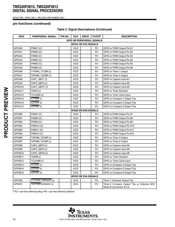
Three capture input pins (CAP1/2/3 for EVA, CAP4/5/6 for EVB)鈥攐ne input pin per capture unit. [All
inputs are synchronized with the device (CPU) clock. In order for a transition to be captured, the input
must hold at its current level to meet two rising edges of the device clock. The input pins CAP1/2 and
CAP4/5 can also be used as QEP inputs to the QEP circuit.]
User-specified transition (rising edge, falling edge, or both edges) detection
Three maskable interrupt flags, one for each capture unit
鈥?/div>
鈥?/div>
quadrature-encoder pulse (QEP) circuit
Two capture inputs (CAP1 and CAP2 for EVA; CAP4 and CAP5 for EVB) can be used to interface the on-chip
QEP circuit with a quadrature encoder pulse. Full synchronization of these inputs is performed on-chip.
Direction or leading-quadrature pulse sequence is detected, and GP timer 2/4 is incremented or decremented
by the rising and falling edges of the two input signals (four times the frequency of either input pulse).
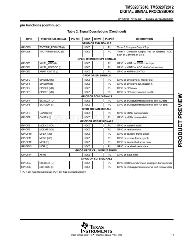
external ADC start-of-conversion
EVA/EVB start-of-conversion (SOC) can be sent to an external pin (ESOCA/B) for external ADC interface.
EVASOC and EVBSOC are muxed with T2CTRIP and T4CTRIP, respectively.
66
POST OFFICE BOX 1443
鈥?/div>
HOUSTON, TEXAS 77251鈥?443


 1
1
 2
2
 3
3
 4
4
 5
5
 6
6
 7
7
 8
8
 9
9
 10
10
 11
11
 12
12
 13
13
 14
14
 15
15
 16
16
 17
17
 18
18
 19
19
 20
20
 21
21
 22
22
 23
23
 24
24
 25
25
 26
26
 27
27
 28
28
 29
29
 30
30
 31
31
 32
32
 33
33
 34
34
 35
35
 36
36
 37
37
 38
38
 39
39
 40
40
 41
41
 42
42
 43
43
 44
44
 45
45
 46
46
 47
47
 48
48
 49
49
 50
50
 51
51
 52
52
 53
53
 54
54
 55
55
 56
56
 57
57
 58
58
 59
59
 60
60
 61
61
 62
62
 63
63
 64
64
 65
65
 66
66
 67
67
 68
68
 69
69
 70
70
 71
71
 72
72
 73
73
 74
74
 75
75
 76
76
 77
77
 78
78
 79
79
 80
80
 81
81
 82
82
 83
83
 84
84
 85
85
 86
86
 87
87
 88
88
 89
89
 90
90
 91
91
 92
92
 93
93
 94
94
 95
95
 96
96
 97
97
 98
98
 99
99
 100
100
 101
101
 102
102
 103
103
