鈥?/div>
XRS,
WDINT,
Any Enabled Interrupt,
XNMI
XRS,
WDINT,
XINT1,
XNMI,
T1/2/3/4CTRIP,
C1/2/3/4/5/6TRIP,
SCIRXDA,
SCIRXDB,
CANRX,
Debugger搂
XRS,
XNMI,
Debugger搂
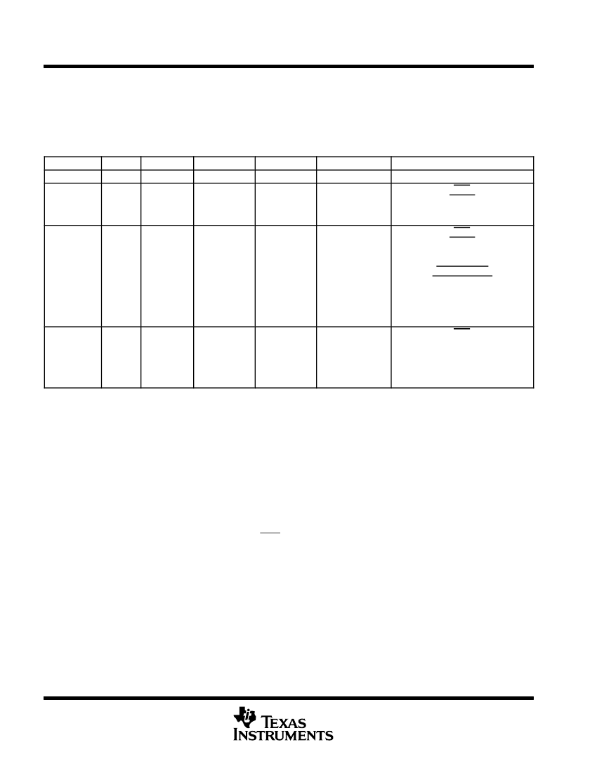
STANDBY
high
0,1
on
(watchdog still
running)
off
off
PRODUCT PREVIEW
HALT
high
1,X
off
(oscillator and
PLL turned
off, watchdog
not functional)
off
off
鈥?The Exit column lists which signals or under what conditions the low power mode will be exited. A low signal, on any of the signals, will exit the
low power condition. This signal must be kept low long enough for an interrupt to be recognized by the device. Otherwise the IDLE mode will
not be exited and the device will go back into the indicated low power mode.
鈥?The IDLE mode on the C28x behaves differently than on the 24x/240x. On the C28x, the clock output from the core (SYSCLKOUT) is still
functional while on the 24x/240x the clock is turned off.
搂 On the C28x, the JTAG port can still function even if the core clock (CLKIN) is turned off.
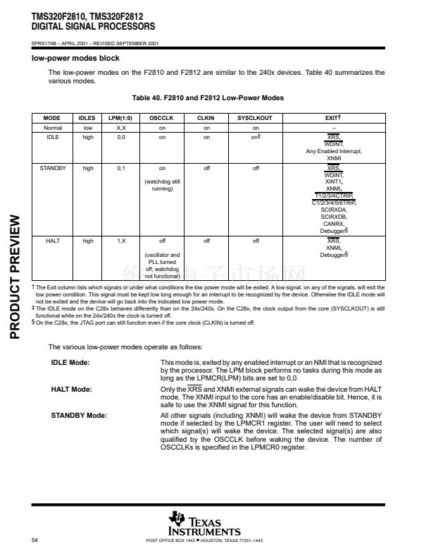
The various low-power modes operate as follows:
IDLE Mode:
This mode is, exited by any enabled interrupt or an NMI that is recognized
by the processor. The LPM block performs no tasks during this mode as
long as the LPMCR(LPM) bits are set to 0,0.
Only the XRS and XNMI external signals can wake the device from HALT
mode. The XNMI input to the core has an enable/disable bit. Hence, it is
safe to use the XNMI signal for this function.
All other signals (including XNMI) will wake the device from STANDBY
mode if selected by the LPMCR1 register. The user will need to select
which signal(s) will wake the device. The selected signal(s) are also
qualified by the OSCCLK before waking the device. The number of
OSCCLKs is specified in the LPMCR0 register.
HALT Mode:
STANDBY Mode:
54
POST OFFICE BOX 1443
鈥?/div>
HOUSTON, TEXAS 77251鈥?443


 1
1
 2
2
 3
3
 4
4
 5
5
 6
6
 7
7
 8
8
 9
9
 10
10
 11
11
 12
12
 13
13
 14
14
 15
15
 16
16
 17
17
 18
18
 19
19
 20
20
 21
21
 22
22
 23
23
 24
24
 25
25
 26
26
 27
27
 28
28
 29
29
 30
30
 31
31
 32
32
 33
33
 34
34
 35
35
 36
36
 37
37
 38
38
 39
39
 40
40
 41
41
 42
42
 43
43
 44
44
 45
45
 46
46
 47
47
 48
48
 49
49
 50
50
 51
51
 52
52
 53
53
 54
54
 55
55
 56
56
 57
57
 58
58
 59
59
 60
60
 61
61
 62
62
 63
63
 64
64
 65
65
 66
66
 67
67
 68
68
 69
69
 70
70
 71
71
 72
72
 73
73
 74
74
 75
75
 76
76
 77
77
 78
78
 79
79
 80
80
 81
81
 82
82
 83
83
 84
84
 85
85
 86
86
 87
87
 88
88
 89
89
 90
90
 91
91
 92
92
 93
93
 94
94
 95
95
 96
96
 97
97
 98
98
 99
99
 100
100
 101
101
 102
102
 103
103
