TMS320F2810, TMS320F2812
DIGITAL SIGNAL PROCESSORS
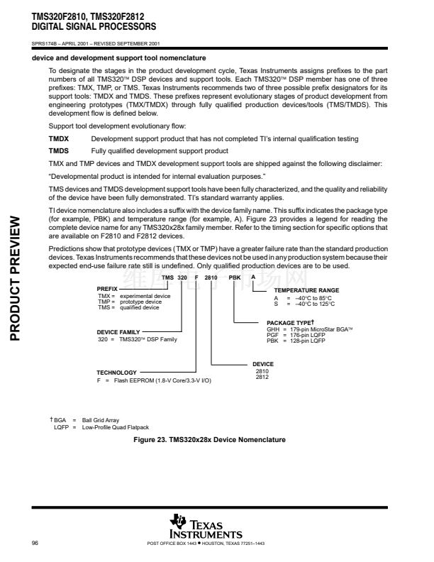
SPRS174B 鈥?APRIL 2001 鈥?REVISED SEPTEMBER 2001
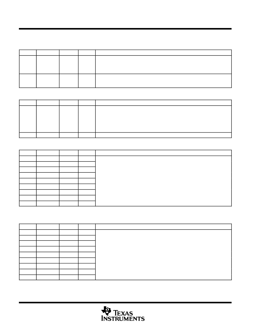
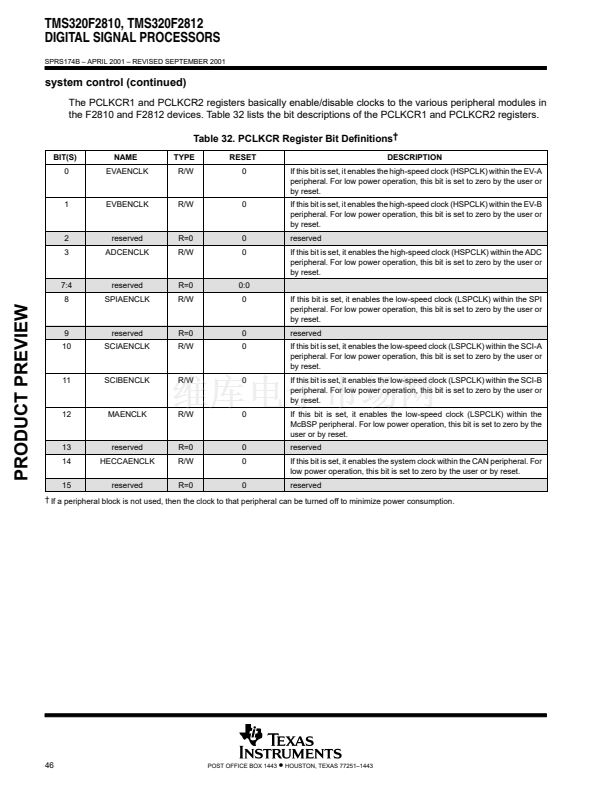
PIE registers (continued)
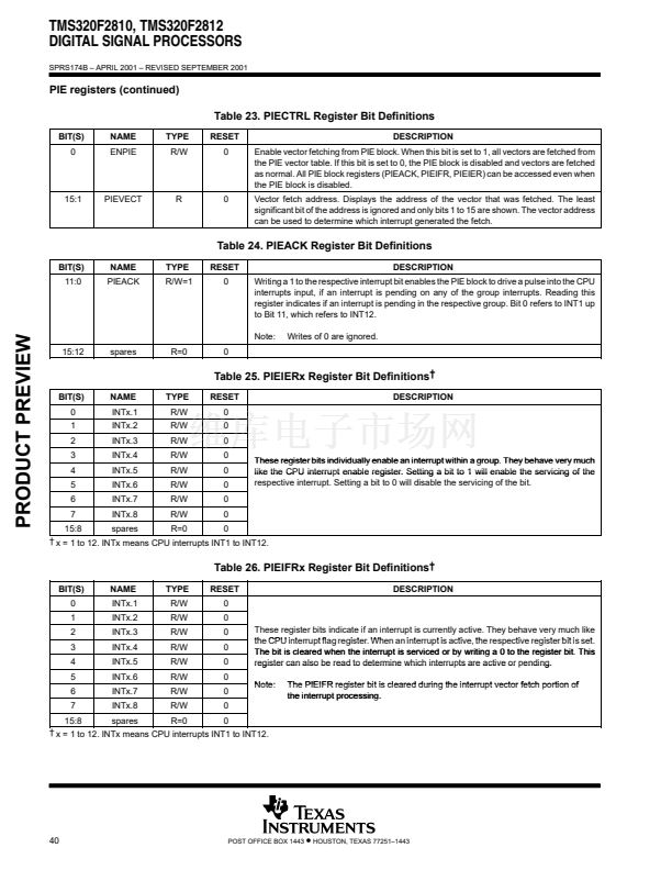
Table 23. PIECTRL Register Bit Definitions
BIT(S)
0
NAME
ENPIE
TYPE
R/W
RESET
0
DESCRIPTION
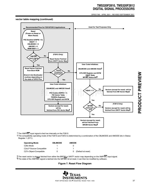
Enable vector fetching from PIE block. When this bit is set to 1, all vectors are fetched from
the PIE vector table. If this bit is set to 0, the PIE block is disabled and vectors are fetched
as normal. All PIE block registers (PIEACK, PIEIFR, PIEIER) can be accessed even when
the PIE block is disabled.
Vector fetch address. Displays the address of the vector that was fetched. The least
significant bit of the address is ignored and only bits 1 to 15 are shown. The vector address
can be used to determine which interrupt generated the fetch.
15:1
PIEVECT
R
0
Table 24. PIEACK Register Bit Definitions
BIT(S)
11:0
NAME
PIEACK
TYPE
R/W=1
RESET
0
DESCRIPTION
Writing a 1 to the respective interrupt bit enables the PIE block to drive a pulse into the CPU
interrupts input, if an interrupt is pending on any of the group interrupts. Reading this
register indicates if an interrupt is pending in the respective group. Bit 0 refers to INT1 up
to Bit 11, which refers to INT12.
Note:
15:12
spares
R=0
0
Writes of 0 are ignored.
PRODUCT PREVIEW
Table 25. PIEIERx Register Bit Definitions
鈥?/div>
BIT(S)
0
1
2
3
4
5
6
7
NAME
INTx.1
INTx.2
INTx.3
INTx.4
INTx.5
INTx.6
INTx.7
INTx.8
TYPE
R/W
R/W
R/W
R/W
R/W
R/W
R/W
R/W
RESET
0
0
0
0
0
0
0
0
These register bits individually enable an interrupt within a group. They behave very much
group
like the CPU interru t enable register. Setting a bit to 1 will enable the servicing of the
interrupt
respective interrupt. Setting a bit to 0 will disable the servicing of the bit.
DESCRIPTION
15:8
spares
R=0
0
鈥?x = 1 to 12. INTx means CPU interrupts INT1 to INT12.
Table 26. PIEIFRx Register Bit Definitions
鈥?/div>
BIT(S)
0
1
2
3
4
5
6
7
15:8
NAME
INTx.1
INTx.2
INTx.3
INTx.4
INTx.5
INTx.6
INTx.7
INTx.8
spares
TYPE
R/W
R/W
R/W
R/W
R/W
R/W
R/W
R/W
R=0
RESET
0
0
0
0
0
0
0
0
0
Note:
The PIEIFR register bit is cleared during the interrupt vector fetch portion of
the interrupt processing.
These register bits indicate if an interrupt is currently active. They behave very much like
the
th CPU i t
interrupt fl register. Wh an i t
t flag
i t When interrupt i active, th respective register bit i set.
t is ti
the
ti
i t
is t
The bit is cleared when the interrupt is serviced or by writing a 0 to the register bit. This
bit
register can also be read to determine which interru ts are active or pending.
interrupts
ending.
DESCRIPTION
鈥?x = 1 to 12. INTx means CPU interrupts INT1 to INT12.
40
POST OFFICE BOX 1443
鈥?/div>
HOUSTON, TEXAS 77251鈥?443


 1
1
 2
2
 3
3
 4
4
 5
5
 6
6
 7
7
 8
8
 9
9
 10
10
 11
11
 12
12
 13
13
 14
14
 15
15
 16
16
 17
17
 18
18
 19
19
 20
20
 21
21
 22
22
 23
23
 24
24
 25
25
 26
26
 27
27
 28
28
 29
29
 30
30
 31
31
 32
32
 33
33
 34
34
 35
35
 36
36
 37
37
 38
38
 39
39
 40
40
 41
41
 42
42
 43
43
 44
44
 45
45
 46
46
 47
47
 48
48
 49
49
 50
50
 51
51
 52
52
 53
53
 54
54
 55
55
 56
56
 57
57
 58
58
 59
59
 60
60
 61
61
 62
62
 63
63
 64
64
 65
65
 66
66
 67
67
 68
68
 69
69
 70
70
 71
71
 72
72
 73
73
 74
74
 75
75
 76
76
 77
77
 78
78
 79
79
 80
80
 81
81
 82
82
 83
83
 84
84
 85
85
 86
86
 87
87
 88
88
 89
89
 90
90
 91
91
 92
92
 93
93
 94
94
 95
95
 96
96
 97
97
 98
98
 99
99
 100
100
 101
101
 102
102
 103
103
