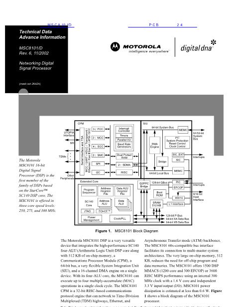
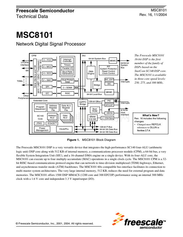
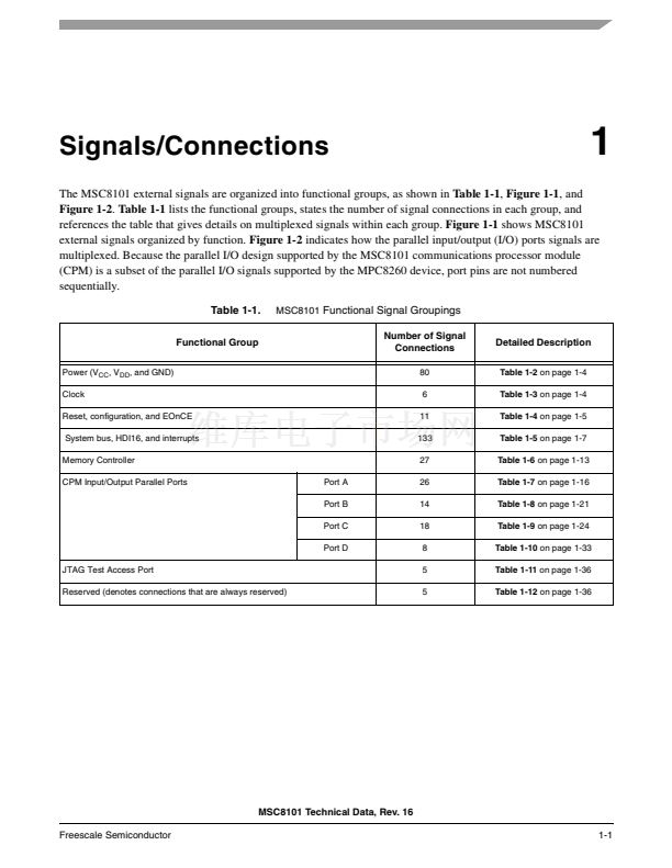
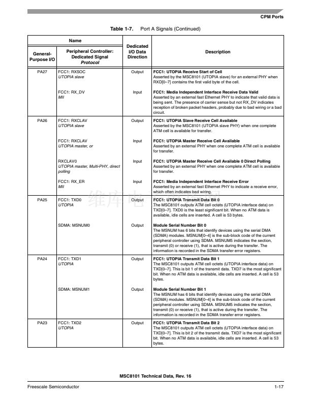
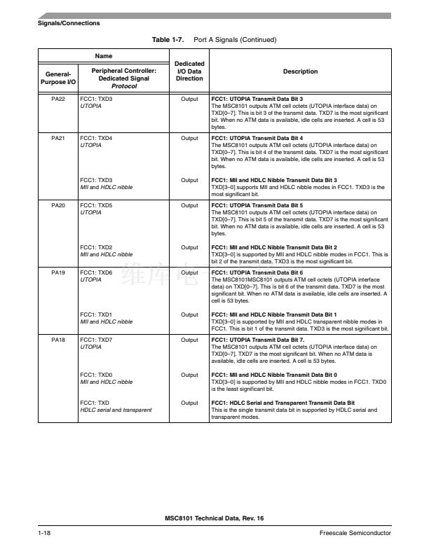
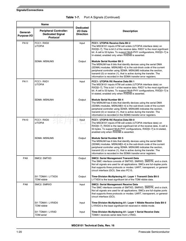
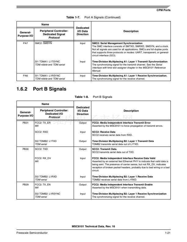
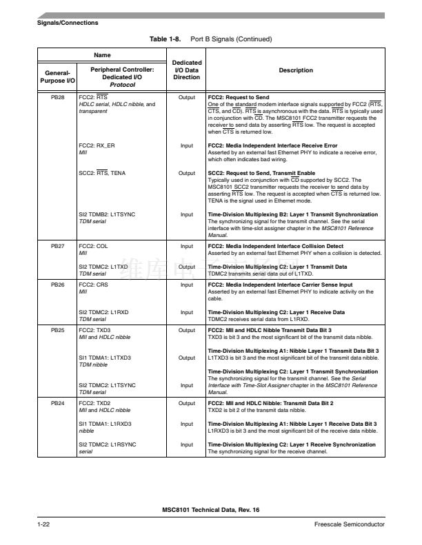
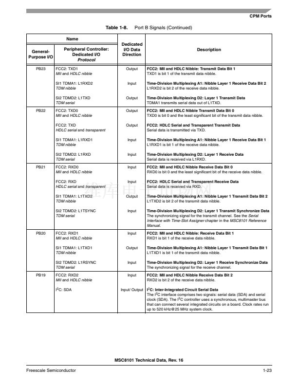
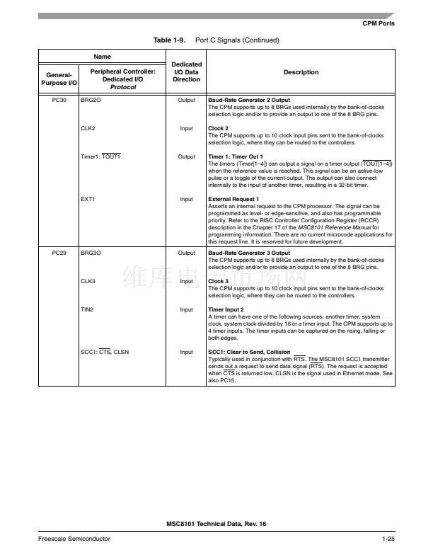
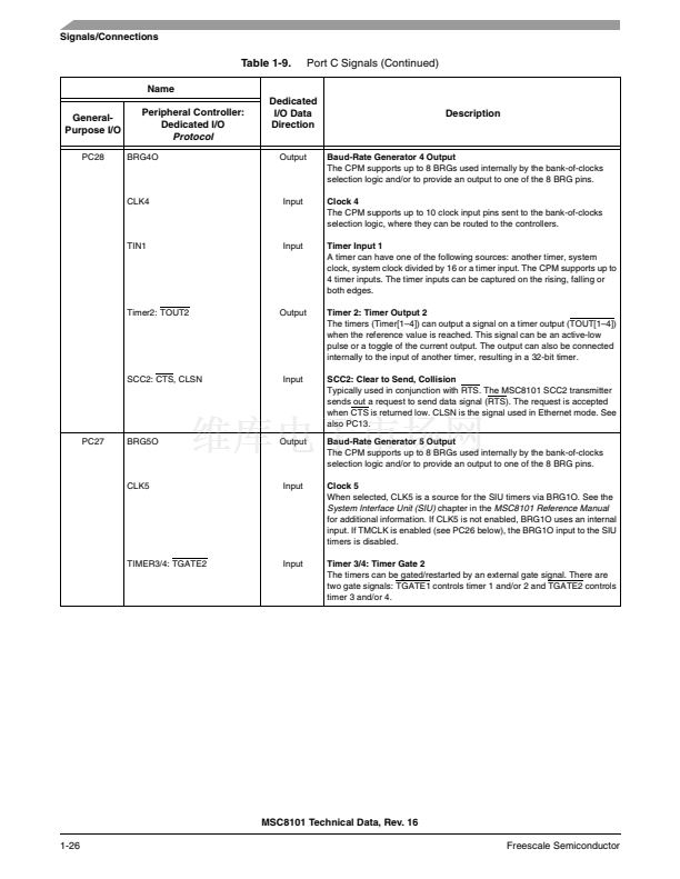
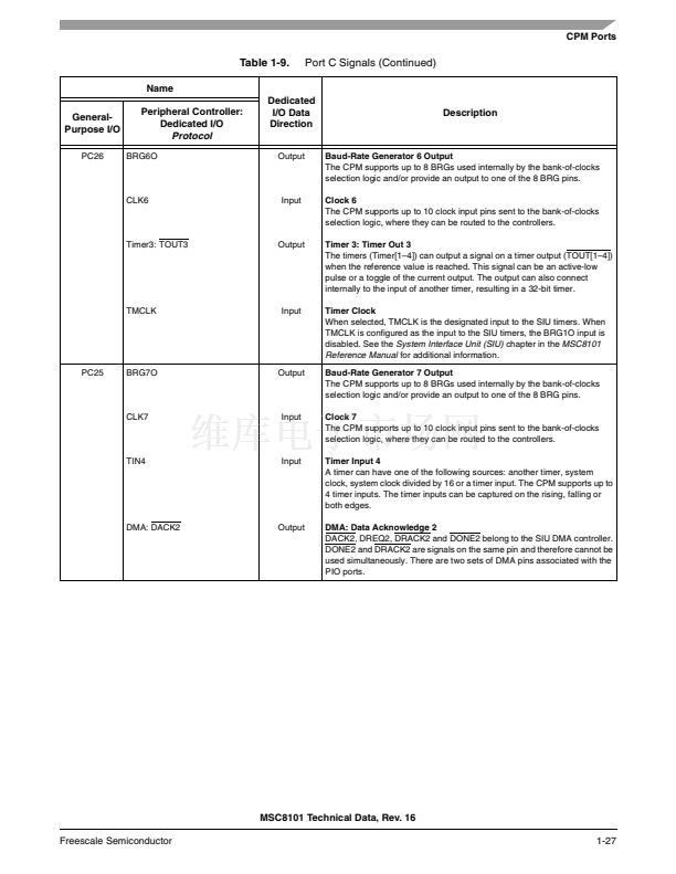
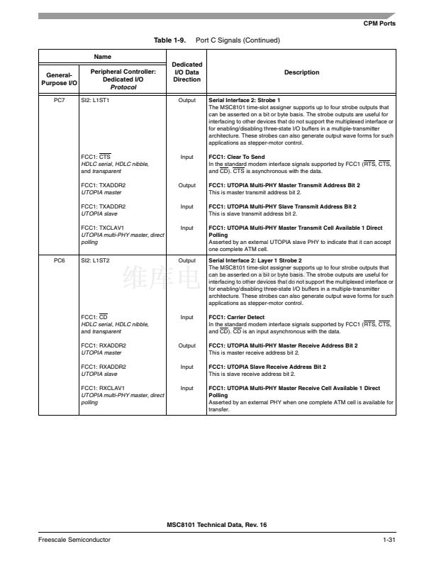
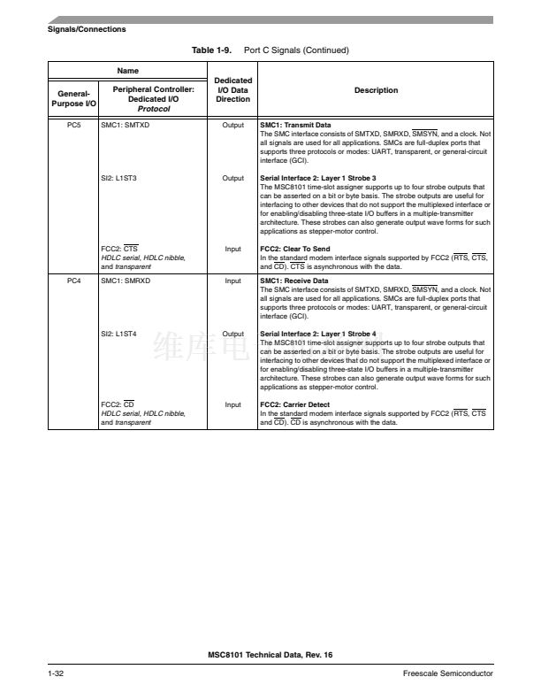
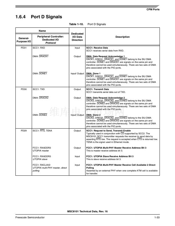
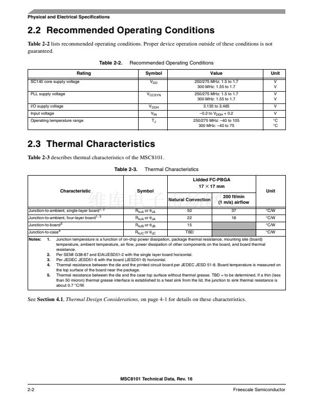
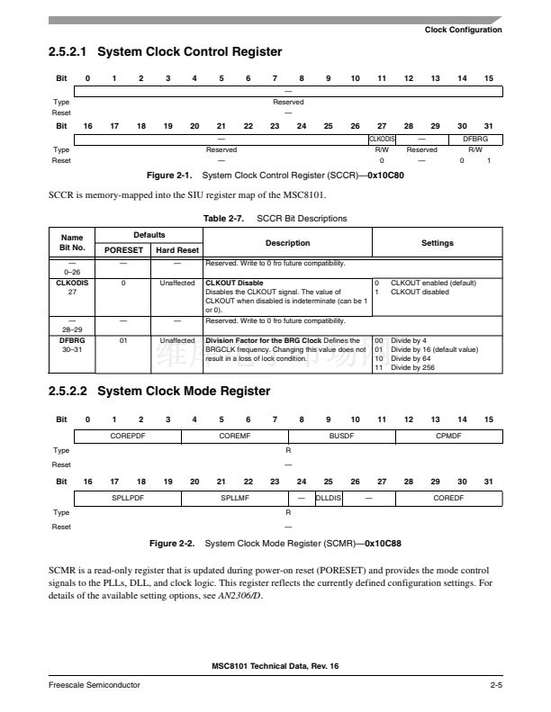
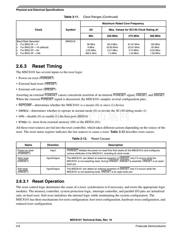
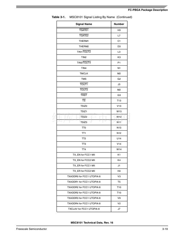
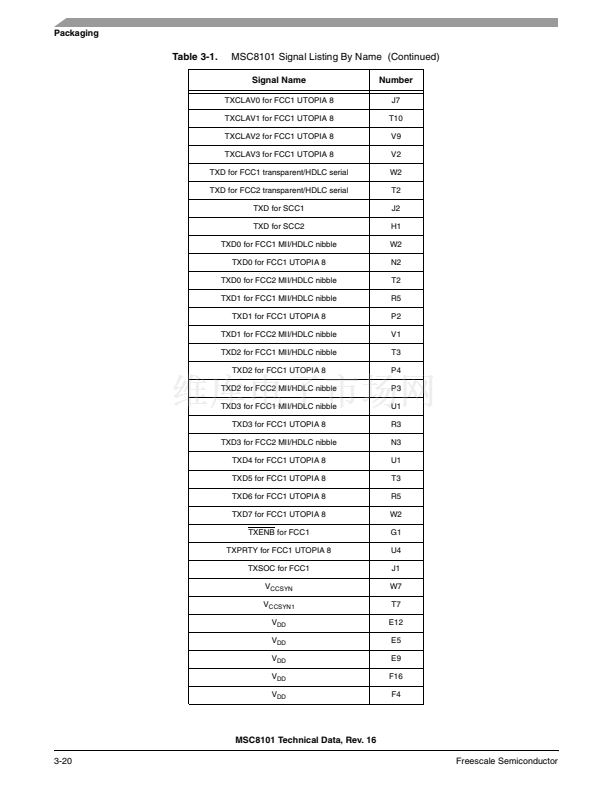
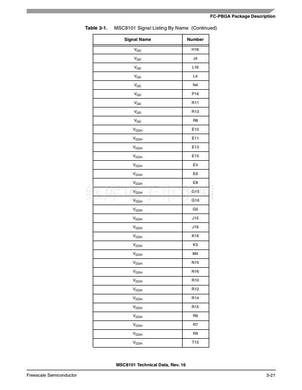
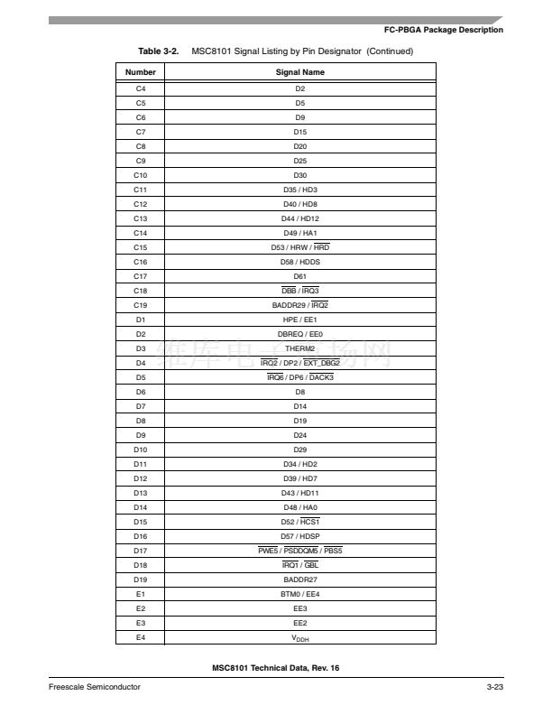
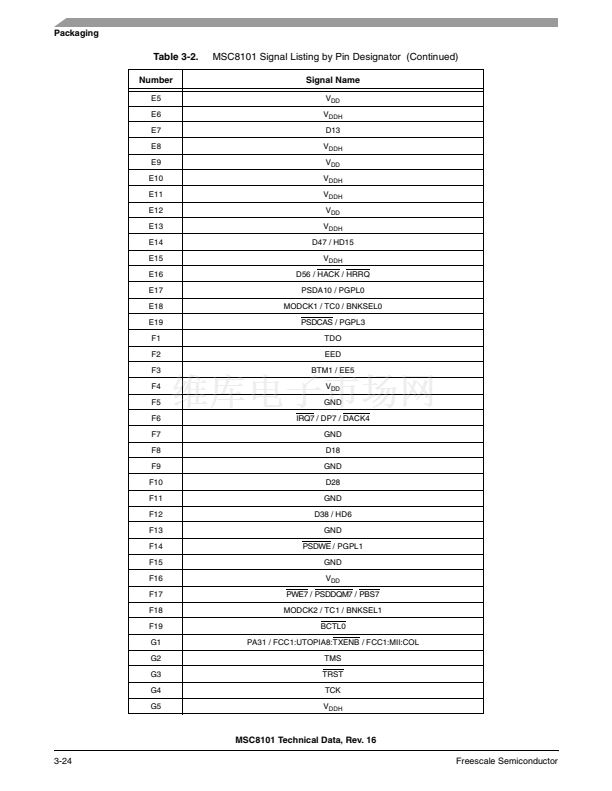
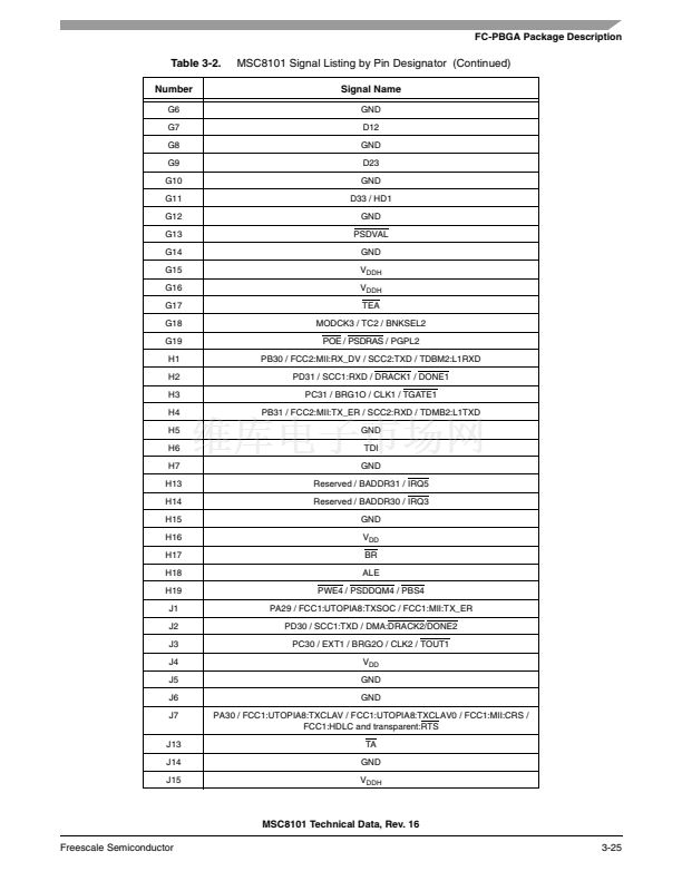
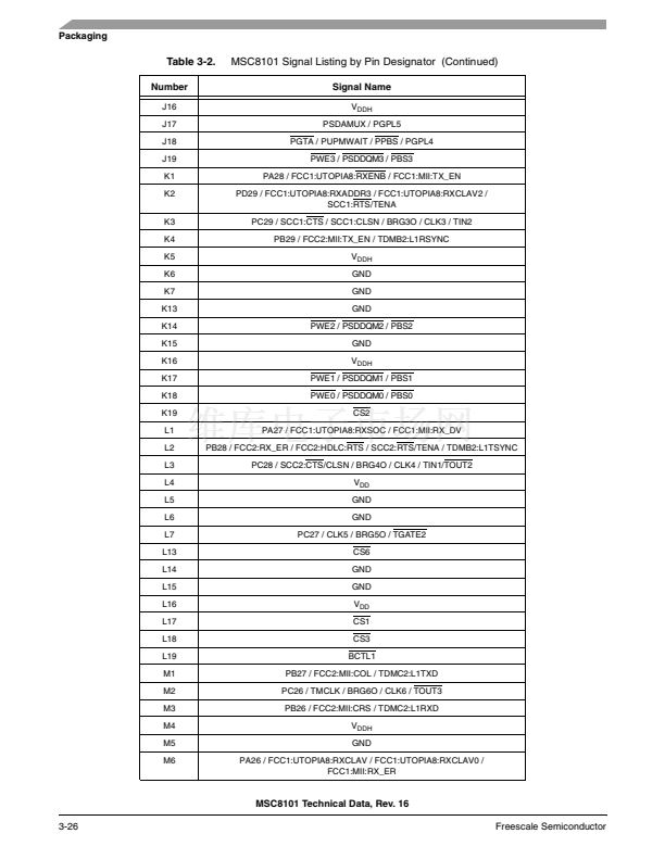
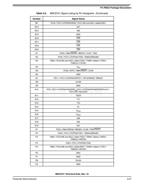
Signals/Connections
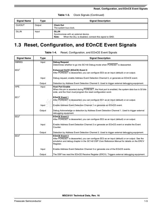
Table 1-4.
Signal Name
BTM[0鈥?]
Reset, Configuration, and EOnCE Event Signals (Continued)
Signal Description
Boot Mode 0鈥?
Determines the MSC8101 boot mode when PORESET is deasserted. See the emulation and debug
chapter in the
SC140 DSP Core Reference Manual
for details on how to set these pins.
EOnCE Event 4
After PORESET is deasserted, you can configure EE4 as an input (default) or an output. See the
emulation and debug chapter in the
SC140 DSP Core Reference Manual
for details on the ETRSMT
Register.
Type
Input
EE4
1
Input
Output
EE5
1
Enable Address Event Detection Channel 4 or generate an EOnCE event.
The DSP wrote the EOnCE Transmit Register (ETRSMT). Triggers external debugging equipment.
EOnCE Event 5
After PORESET is deasserted, you can configure EE5 as an input (default) or an output.
Input
Output
EED
1
Enable Address Event Detection Channel 5.
Detection by Address Event Detection Channel 5. Triggers external debugging equipment.
Enhanced OnCE (EOnCE) Event Detection
After PORESET is deasserted, you can configure EED as an input (default) or output:
Input
Output
PORESET
RSTCONF
Input
Input
Enable the Data Event Detection Channel.
Detection by the Data Event Detection Channel. Triggers external debugging equipment.
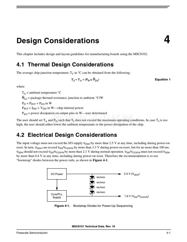
Power-On Reset
When asserted, this line causes the MSC8101 to enter power-on reset state.
Reset Configuration
Used during reset configuration sequence of the chip. A detailed explanation of its function is
provided in the 鈥淧ower-On Reset Flow鈥?and 鈥淗ardware Reset Configuration鈥?sections of the
MSC8101 Reference Manual.
Hard Reset
When asserted, this open-drain line causes the MSC8101 to enter the hard reset state.
Soft Reset
When asserted, this open-drain line causes the MSC8101 to enter the soft reset state.
HRESET
SRESET
Note:
Input
Input
See the emulation and debug chapter in the
SC140 DSP Core Reference Manual
for details on how to configure these pins.
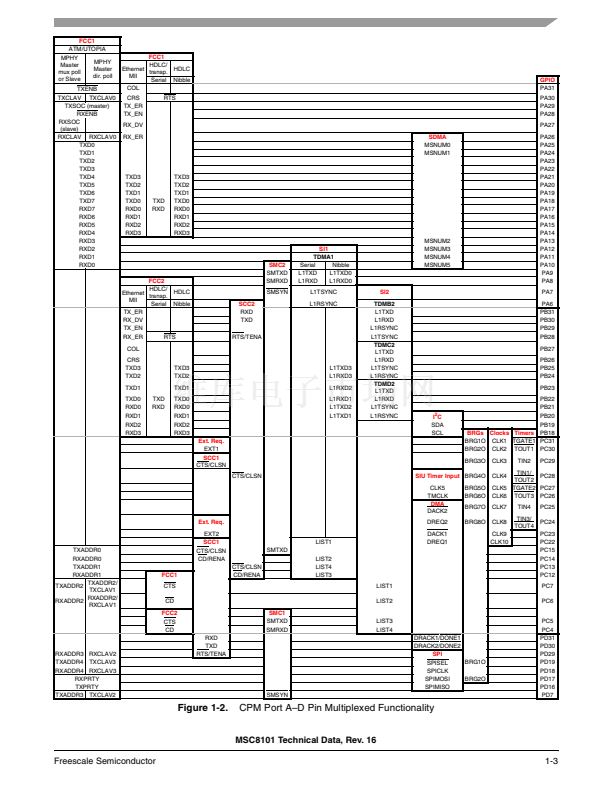
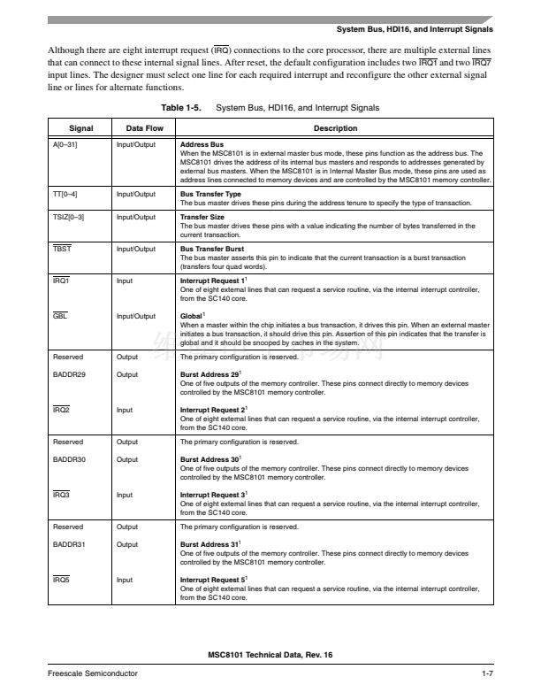
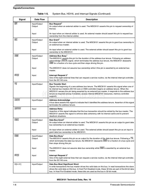
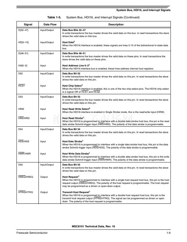
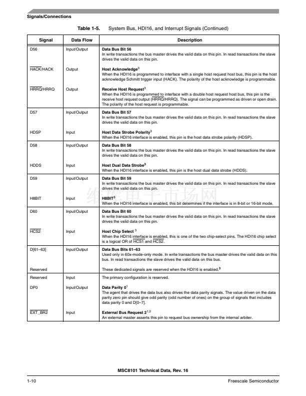
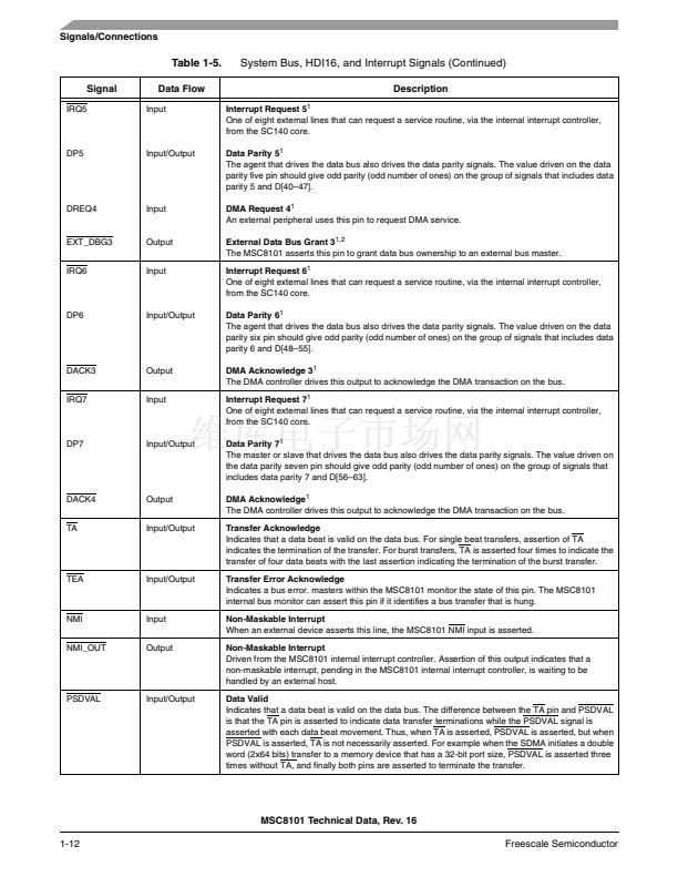
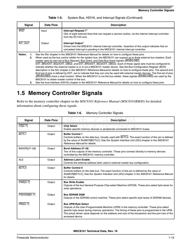
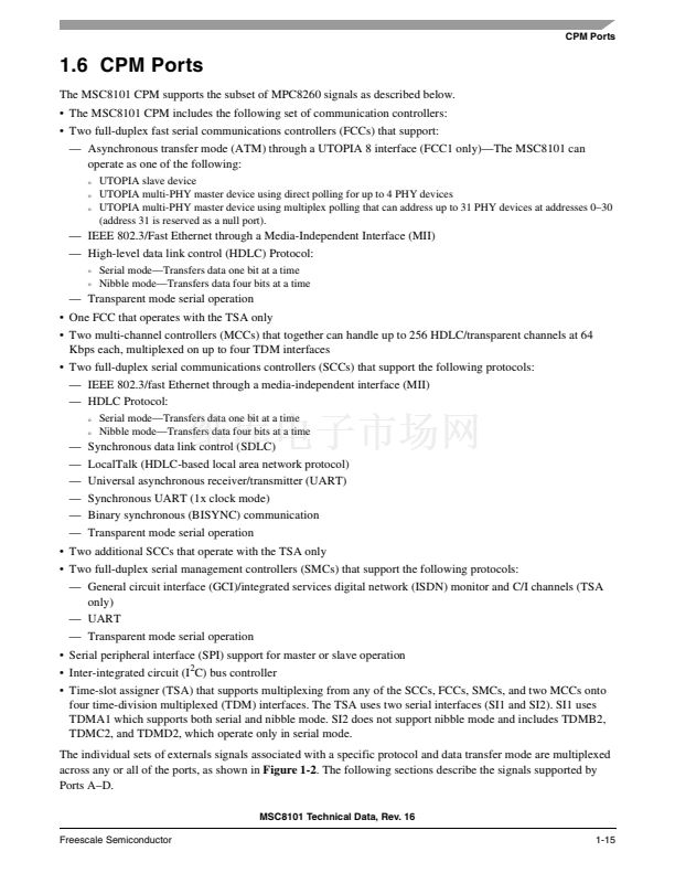
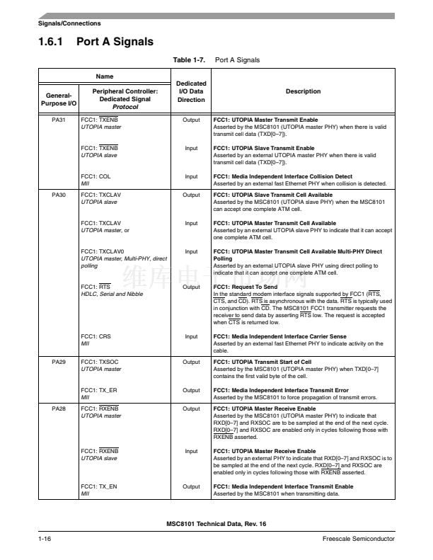
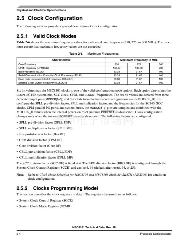
1.4 System Bus, HDI16, and Interrupt Signals
The system bus, HDI16, and interrupt signals are grouped together because they use a common set of signal lines.
Individual assignment of a signal to a specific signal line is configured through registers in the System Interface
Unit (SIU) and the Host Interface (HDI16). 1-5 describes the signals in this group.
Note:
To boot from the host interface, the HDI16 must be enabled by pulling up the
HPE
signal line during
PORESET
. The configuration word must then be loaded from the host. The configuration word must set the
Internal Space Port Size bit in the Bus Control Register (BCR[ISPS]) to change the system data bus width
from 64 bits to 32 bits and reassign the upper 32 bits to their HDI16 functions. Never set the Host Port
Enable (HEN) bit in the Host Port Control Register (HPCR) to enable the HDI16, unless the bus size is
first changed from 64 bits to 32 bits. Otherwise, unpredictable operation may occur.
MSC8101 Technical Data, Rev. 16
1-6
Freescale Semiconductor


 1
1
 2
2
 3
3
 4
4
 5
5
 6
6
 7
7
 8
8
 9
9
 10
10
 11
11
 12
12
 13
13
 14
14
 15
15
 16
16
 17
17
 18
18
 19
19
 20
20
 21
21
 22
22
 23
23
 24
24
 25
25
 26
26
 27
27
 28
28
 29
29
 30
30
 31
31
 32
32
 33
33
 34
34
 35
35
 36
36
 37
37
 38
38
 39
39
 40
40
 41
41
 42
42
 43
43
 44
44
 45
45
 46
46
 47
47
 48
48
 49
49
 50
50
 51
51
 52
52
 53
53
 54
54
 55
55
 56
56
 57
57
 58
58
 59
59
 60
60
 61
61
 62
62
 63
63
 64
64
 65
65
 66
66
 67
67
 68
68
 69
69
 70
70
 71
71
 72
72
 73
73
 74
74
 75
75
 76
76
 77
77
 78
78
 79
79
 80
80
 81
81
 82
82
 83
83
 84
84
 85
85
 86
86
 87
87
 88
88
 89
89
 90
90
 91
91
 92
92
 93
93
 94
94
 95
95
 96
96
 97
97
 98
98
 99
99
 100
100
 101
101
 102
102
 103
103
 104
104
