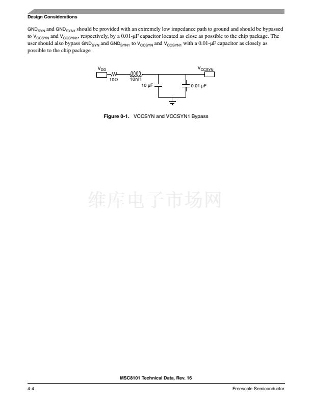
Design Considerations
Select the bootstrap diodes such that a nominal V
DD
/V
CCSYN
is sourced from the
V
DDH
power supply until the
V
DD
/
V
CCSYN
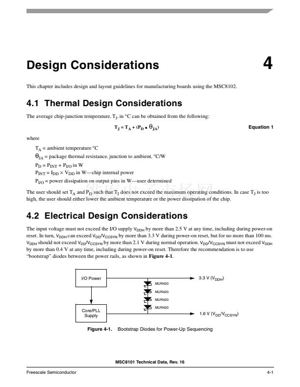
power supply becomes active. In
Figure 4-1,
four MUR420 Schottky barrier diodes are connected in
series; each has a forward voltage (V
F
) of 0.6 V at high currents, so these diodes provide a 2.4 V drop, maintaining
0.9 V on the 1.6 V power line. Once the core/PLL power supply stabilizes at 1.6 V, the bootstrap diodes will be
reverse biased with negligible leakage current. The V
F
should be effective at the current levels required by the
processor. Do not use diodes with a nominal V
F
that drops too low at high current.
4.3 Power Considerations
The internal power dissipation consists of three components:
P
INT
= P
CORE
+ P
SIU
+ P
CPM
Power dissipation depends on the operating frequency of the different portions of the chip.
Table 2-5
provides
typical power values at the specified operating frequencies. To determine the typical power dissipation for a given
set of frequencies, use the following equations:
P
CORE
(f) = ((P
CORE
鈥?P
LCO
)/f
CORE
)
脳
f
COREA
+ P
LCO
P
CPM
(f) = ((P
CPM
鈥?P
LCP
)/f
CPM
)
脳
f
CPMA
+ P
LCP
P
SIU
(f) = ((P
SIU
鈥?P
LSI
)/f
SIU
)
脳
f
SIUA
+ P
LSI
Where:
f
CORE
is the core frequency, f
SIU
is the SIU frequency, and f
CPM
is the CPM frequency specified in
Table 2-5
in MHz
f
COREA
is the actual core frequency, F
SIUA
is the actual SIU frequency, and F
CPMA
is the actual CPM fre-
quency in MHz
P
LCO
, P
LSI
, and P
LCP
are the leakage power values specified in
Table 2-5
All power numbers are in mW
Power consumption is assumed to be linear with frequency. The first part of each equation computes a
mw/MHz value that is then scaled based on the actual frequency used.
To determine a total power dissipation in a specific application, you must add the power values derived from the
above set of equations to the value derived for I/O power consumption using the following equation for each output
pin:
P = C
脳
V
DDH2
脳
f
脳
10
鈥?
Equation 2
Where: P = power in mW, C = load capacitance in pF, f = output switching frequency in MHz.
For an application in which external data memory is used in a 32-bit single bus mode and no other outputs are
active, the core runs at 200 MHz, the CPM runs at 100 MHz and the SIU runs at 50 MHz, power dissipation is
calculated as follows:
Assumptions:
鈥?External data memory is accessed every second cycle with 10% of address pins switching.
鈥?External data memory writes occurs once every eight cycles with 50% of data pins switching.
鈥?Each address and data pin has a 30 pF total load at the pin.
鈥?The application operates at
V
DDH
= 3.3 V.
MSC8101 Technical Data, Rev. 16
4-2
Freescale Semiconductor


 1
1
 2
2
 3
3
 4
4
 5
5
 6
6
 7
7
 8
8
 9
9
 10
10
 11
11
 12
12
 13
13
 14
14
 15
15
 16
16
 17
17
 18
18
 19
19
 20
20
 21
21
 22
22
 23
23
 24
24
 25
25
 26
26
 27
27
 28
28
 29
29
 30
30
 31
31
 32
32
 33
33
 34
34
 35
35
 36
36
 37
37
 38
38
 39
39
 40
40
 41
41
 42
42
 43
43
 44
44
 45
45
 46
46
 47
47
 48
48
 49
49
 50
50
 51
51
 52
52
 53
53
 54
54
 55
55
 56
56
 57
57
 58
58
 59
59
 60
60
 61
61
 62
62
 63
63
 64
64
 65
65
 66
66
 67
67
 68
68
 69
69
 70
70
 71
71
 72
72
 73
73
 74
74
 75
75
 76
76
 77
77
 78
78
 79
79
 80
80
 81
81
 82
82
 83
83
 84
84
 85
85
 86
86
 87
87
 88
88
 89
89
 90
90
 91
91
 92
92
 93
93
 94
94
 95
95
 96
96
 97
97
 98
98
 99
99
 100
100
 101
101
 102
102
 103
103
 104
104
