Signals/Connections
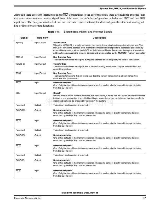
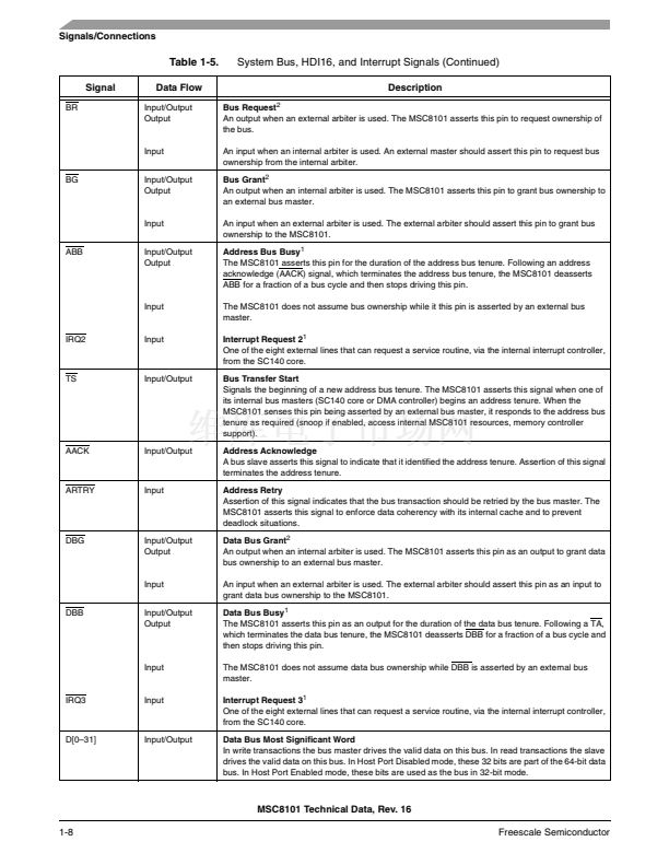
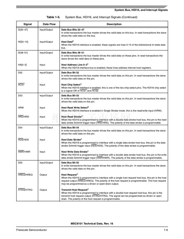
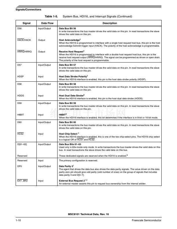
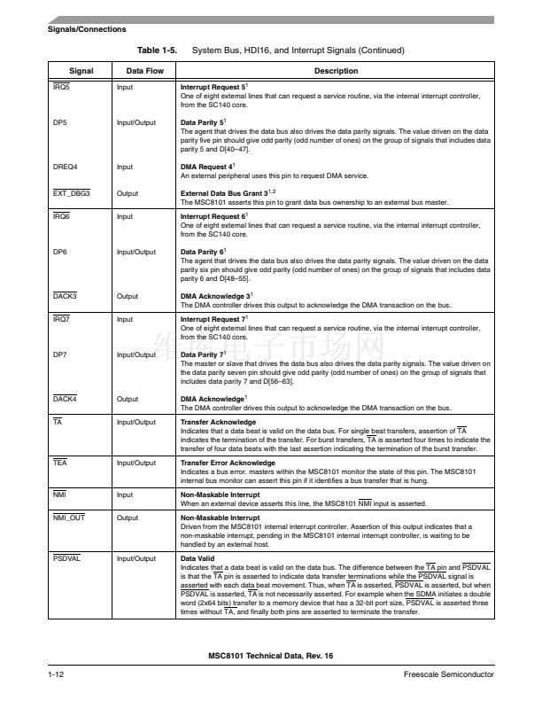
Table 1-5.
Signal
IRQ5
System Bus, HDI16, and Interrupt Signals (Continued)
Description
Interrupt Request 5
1
One of eight external lines that can request a service routine, via the internal interrupt controller,
from the SC140 core.
Data Parity 5
1
The agent that drives the data bus also drives the data parity signals. The value driven on the data
parity five pin should give odd parity (odd number of ones) on the group of signals that includes data
parity 5 and D[40鈥?7].
DMA Request 4
1
An external peripheral uses this pin to request DMA service.
External Data Bus Grant 3
1,2
The MSC8101 asserts this pin to grant data bus ownership to an external bus master.
Interrupt Request 6
1
One of eight external lines that can request a service routine, via the internal interrupt controller,
from the SC140 core.
Data Parity 6
1
The agent that drives the data bus also drives the data parity signals. The value driven on the data
parity six pin should give odd parity (odd number of ones) on the group of signals that includes data
parity 6 and D[48鈥?5].
DMA Acknowledge 3
1
The DMA controller drives this output to acknowledge the DMA transaction on the bus.
Interrupt Request 7
1
One of eight external lines that can request a service routine, via the internal interrupt controller,
from the SC140 core.
Data Parity 7
1
The master or slave that drives the data bus also drives the data parity signals. The value driven on
the data parity seven pin should give odd parity (odd number of ones) on the group of signals that
includes data parity 7 and D[56鈥?3].
DMA Acknowledge
1
The DMA controller drives this output to acknowledge the DMA transaction on the bus.
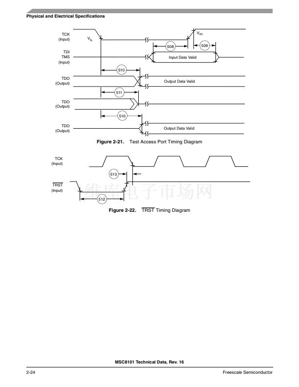
Transfer Acknowledge
Indicates that a data beat is valid on the data bus. For single beat transfers, assertion of TA
indicates the termination of the transfer. For burst transfers, TA is asserted four times to indicate the
transfer of four data beats with the last assertion indicating the termination of the burst transfer.
Transfer Error Acknowledge
Indicates a bus error. masters within the MSC8101 monitor the state of this pin. The MSC8101
internal bus monitor can assert this pin if it identifies a bus transfer that is hung.
Non-Maskable Interrupt
When an external device asserts this line, the MSC8101 NMI input is asserted.
Non-Maskable Interrupt
Driven from the MSC8101 internal interrupt controller. Assertion of this output indicates that a
non-maskable interrupt, pending in the MSC8101 internal interrupt controller, is waiting to be
handled by an external host.
Data Valid
Indicates that a data beat is valid on the data bus. The difference between the TA pin and PSDVAL
is that the TA pin is asserted to indicate data transfer terminations while the PSDVAL signal is
asserted with each data beat movement. Thus, when TA is asserted, PSDVAL is asserted, but when
PSDVAL is asserted, TA is not necessarily asserted. For example when the SDMA initiates a double
word (2x64 bits) transfer to a memory device that has a 32-bit port size, PSDVAL is asserted three
times without TA, and finally both pins are asserted to terminate the transfer.
Data Flow
Input
DP5
Input/Output
DREQ4
Input
EXT_DBG3
IRQ6
Output
Input
DP6
Input/Output
DACK3
IRQ7
Output
Input
DP7
Input/Output
DACK4
TA
Output
Input/Output
TEA
Input/Output
NMI
NMI_OUT
Input
Output
PSDVAL
Input/Output
MSC8101 Technical Data, Rev. 16
1-12
Freescale Semiconductor


 1
1
 2
2
 3
3
 4
4
 5
5
 6
6
 7
7
 8
8
 9
9
 10
10
 11
11
 12
12
 13
13
 14
14
 15
15
 16
16
 17
17
 18
18
 19
19
 20
20
 21
21
 22
22
 23
23
 24
24
 25
25
 26
26
 27
27
 28
28
 29
29
 30
30
 31
31
 32
32
 33
33
 34
34
 35
35
 36
36
 37
37
 38
38
 39
39
 40
40
 41
41
 42
42
 43
43
 44
44
 45
45
 46
46
 47
47
 48
48
 49
49
 50
50
 51
51
 52
52
 53
53
 54
54
 55
55
 56
56
 57
57
 58
58
 59
59
 60
60
 61
61
 62
62
 63
63
 64
64
 65
65
 66
66
 67
67
 68
68
 69
69
 70
70
 71
71
 72
72
 73
73
 74
74
 75
75
 76
76
 77
77
 78
78
 79
79
 80
80
 81
81
 82
82
 83
83
 84
84
 85
85
 86
86
 87
87
 88
88
 89
89
 90
90
 91
91
 92
92
 93
93
 94
94
 95
95
 96
96
 97
97
 98
98
 99
99
 100
100
 101
101
 102
102
 103
103
 104
104
