and 鈥渃onfiguration slave.鈥?/div>
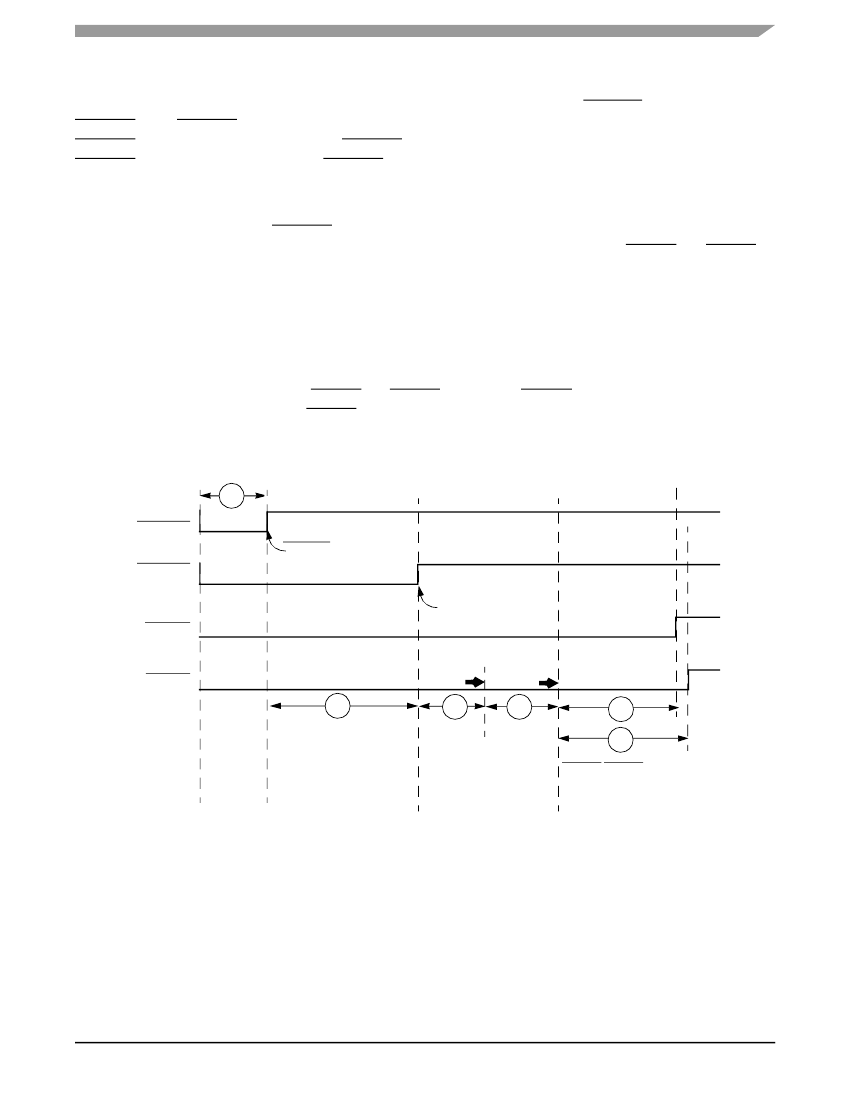
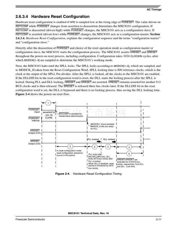
Directly after the deassertion of
PORESET
and choice of the reset operation mode as configuration master or
configuration slave, the MSC8101 starts the configuration process. The MSC8101 asserts
HRESET
and
SRESET
throughout the power-on reset process, including configuration. Configuration takes 1024
CLOCKIN
cycles, after
which
MODCK[1鈥?]
are sampled to determine the MSC8101鈥檚 working mode.
Next, the MSC8101 halts until the SPLL locks. The SPLL locks according to
MODCK[1鈥?]
, which are sampled, and
to MODCK_H taken from the Reset Configuration Word. SPLL locking time is 800 reference clocks, which is the
clock at the output of the SPLL Pre-divider. After the SPLL is locked, all the clocks to the MSC8101 are enabled.
If the DLLDIS bit in the reset configuration word is reset, the DLL starts the locking process after the SPLL is
locked. During PLL and DLL locking,
HRESET
and
SRESET
are asserted.
HRESET
remains asserted for another 512
BUS clocks and is then released. The
SRESET
is released three bus clocks later. If the DLLDIS bit in the reset
configuration word is set, the DLL is bypassed and there is no locking process, thus saving the DLL locking time.
Figure 2-4
shows the power-on reset flow.
1
PORESET
Input
PORESET
Internal
asserted for
min 16
CLKIN.
RSTCONF is sampled for
master/slave determination
HRESET
Output (I/O)
MODCK[1鈥?] are sampled.
MODCK_H bits are ready
for PLL.
SRESET
Output (I/O)
2
In reset configuration mode:
reset configuration sequence
occurs in this period.
PLL locked
3
DLL locked
4
5
6
HRESET/SRESET are
extended for 512/515 bus
clocks, respectively, from PLL
and DLL Lock time.
PLL locks after
800 SPLLMFCLKs. DLL
locks 3073 bus clocks after
PLL is locked.
When DLL is disabled, reset
period is shortened by 3073
bus clocks.
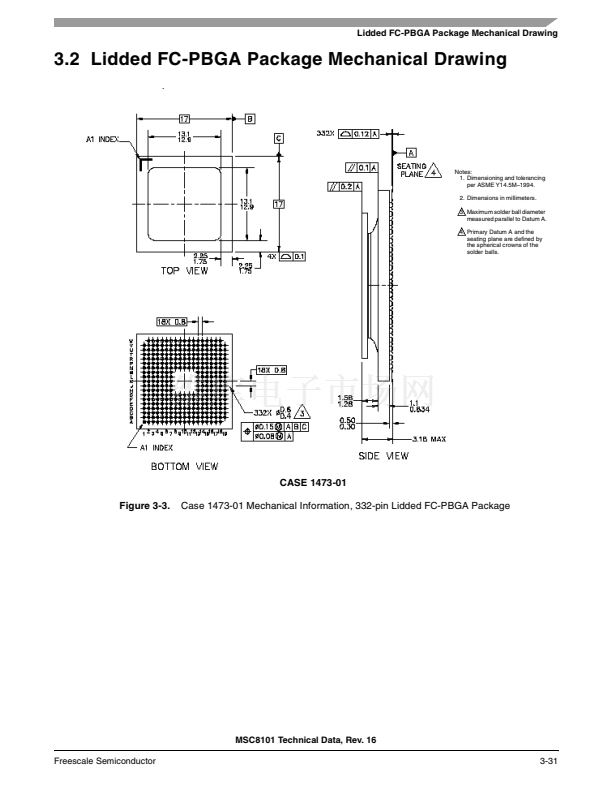
Figure 2-4.
Hardware Reset Configuration Timing
MSC8101 Technical Data, Rev. 16
Freescale Semiconductor
2-11


 1
1
 2
2
 3
3
 4
4
 5
5
 6
6
 7
7
 8
8
 9
9
 10
10
 11
11
 12
12
 13
13
 14
14
 15
15
 16
16
 17
17
 18
18
 19
19
 20
20
 21
21
 22
22
 23
23
 24
24
 25
25
 26
26
 27
27
 28
28
 29
29
 30
30
 31
31
 32
32
 33
33
 34
34
 35
35
 36
36
 37
37
 38
38
 39
39
 40
40
 41
41
 42
42
 43
43
 44
44
 45
45
 46
46
 47
47
 48
48
 49
49
 50
50
 51
51
 52
52
 53
53
 54
54
 55
55
 56
56
 57
57
 58
58
 59
59
 60
60
 61
61
 62
62
 63
63
 64
64
 65
65
 66
66
 67
67
 68
68
 69
69
 70
70
 71
71
 72
72
 73
73
 74
74
 75
75
 76
76
 77
77
 78
78
 79
79
 80
80
 81
81
 82
82
 83
83
 84
84
 85
85
 86
86
 87
87
 88
88
 89
89
 90
90
 91
91
 92
92
 93
93
 94
94
 95
95
 96
96
 97
97
 98
98
 99
99
 100
100
 101
101
 102
102
 103
103
 104
104
